Nissan GT-R (2007-2014 year). INSTRUMENT PANEL / LAN SYSTEM / MAINTENANCE. Service Manual - part 2
INSTRUMENT PANEL ASSEMBLY
IP-17
< REMOVAL AND INSTALLATION >
C
D
E
F
G
H
I
K
L
M
A
B
IP
N
O
P
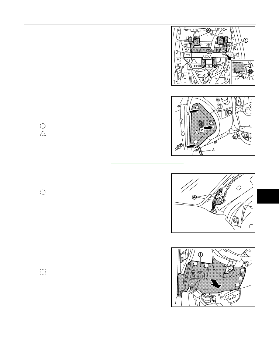
1.
Remove fixing screws (A) of A/C auto amp (1).
2.
Disengage joint of harness clamp (B).
3.
Pull back A/C auto amp.
4.
Disconnect harness connectors on the back.
14. Remove instrument side finisher LH.
1.
Insert remover tool (A) between instrument side finisher LH
(1) and instrument panel assembly.
2.
Pull instrument side finisher LH in lateral direction of vehicle
in order from 1 - 3, and then disengage clip and pawls.
15. Remove body side welt LH. Refer to
INT-15, "Removal and Installation"
.
16. Remove front pillar garnish LH. Refer to
INT-15, "Removal and Installation"
17. Disconnect harness connectors (A) from front pillar LH and
remove clips.
18. Remove instrument lower panel (driver).
1.
Remove hood opener lever mounting bolts.
2.
Pull back instrument lower panel (driver) (1) toward vehicle
lower, and then disengage metal clips.
3.
Disconnect harness connectors on the back.
19. Remove steering wheel. Refer to
ST-10, "Removal and Installation"
.
20. Remove steering column front lower cover.
NNJIA0063ZZ
: Clip
: Pawl
JMJIA2184ZZ
: Clip
JMJIA2185ZZ
: Metal clip
JMJIA2186ZZ
Revision: 2012 November
2014 GT-R