Nissan GT-R (2007-2014 year). EXHAUST SYSTEM / EXTERIOR LIGHTING SYSTEM. Service Manual - part 2
EXL-14
< SYSTEM DESCRIPTION >
[XENON TYPE]
BACK-UP LAMP SYSTEM
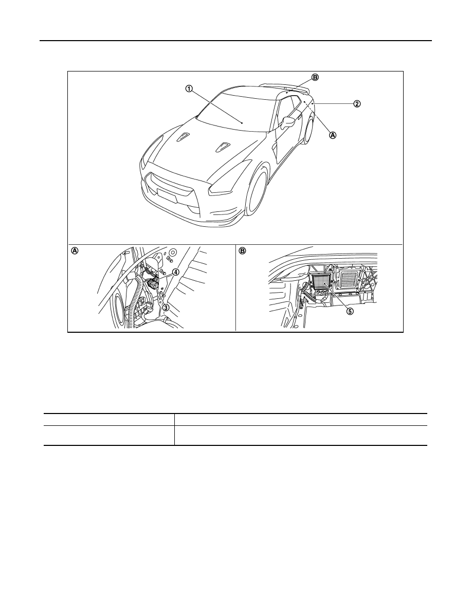
Component Parts Location
INFOID:0000000009160305
Component Description
INFOID:0000000009160306
1.
Control device
2.
Back-up lamp
3.
TCM relay
4.
Back-up lamp relay
5.
TCM
A.
Inside of rear wheel house finisher
(LH)
B.
Inside of trunk front finisher
NNLIA0021ZZ
Part
Description
TCM
• Detects the control device condition.
• Judges the back-up lamp relay ON/OFF by shift lever position status.
Revision: 2012 November
2014 GT-R