Nissan GT-R (2007-2014 year). AUDIO, VISUAL & NAVIGATION SYSTEM. Service Manual - part 6
AV
TWEETER
AV-81
< REMOVAL AND INSTALLATION >
[BASE AUDIO WITH NAVIGATION]
C
D
E
F
G
H
I
J
K
L
M
B
A
O
P
TWEETER
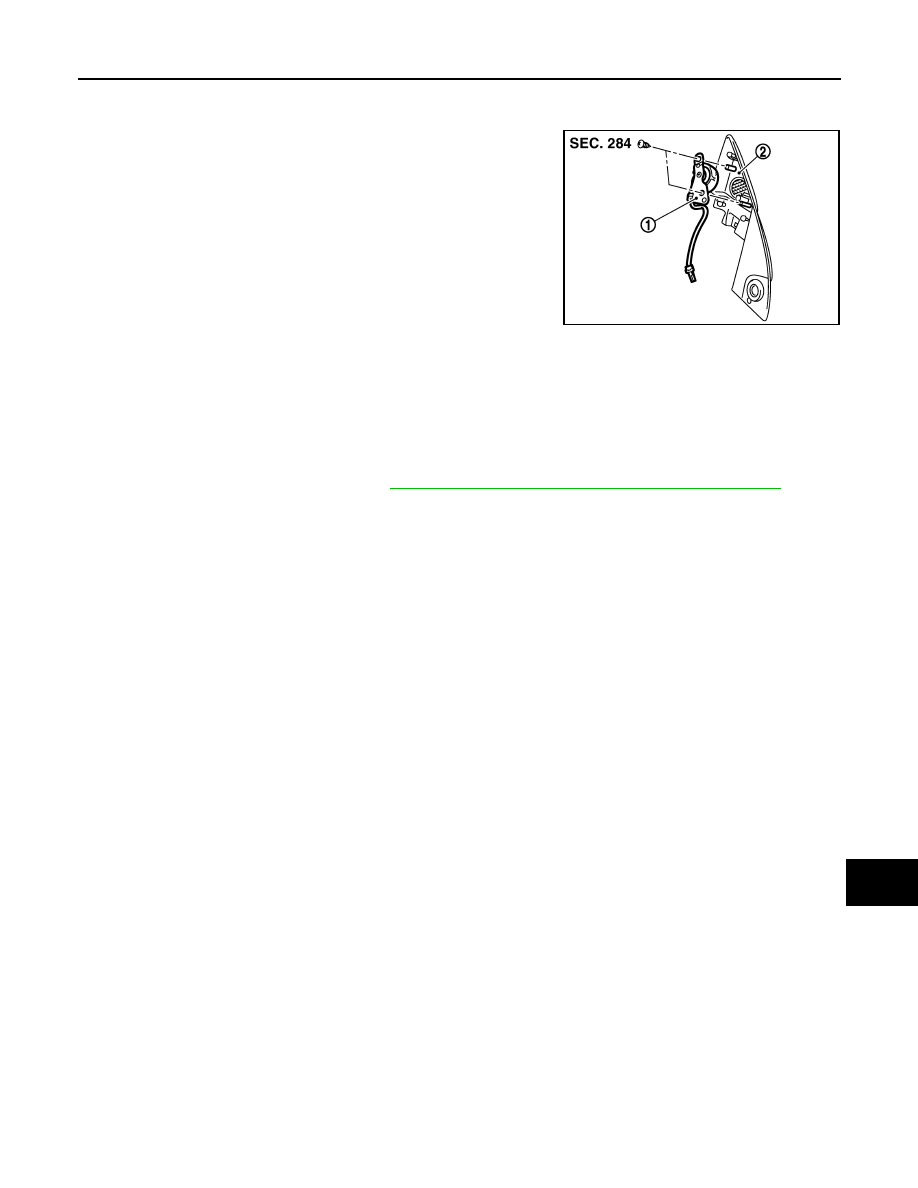
Exploded View
INFOID:0000000009163300
Removal and Installation
INFOID:0000000009163301
REMOVAL
1.
Remove the door corner cover. Refer to
MIR-16, "DOOR MIRROR ASSEMBLY : Exploded View"
.
2.
Remove the screws, and remove the tweeter from the door corner cover.
INSTALLATION
Install in the reverse order of removal.
NNNIA0039ZZ
1.
Tweeter
2.
Door corner cover
Revision: 2012 November
2014 GT-R