содержание .. 297 298 299 300 ..
Nissan GT-R. Manual - part 299
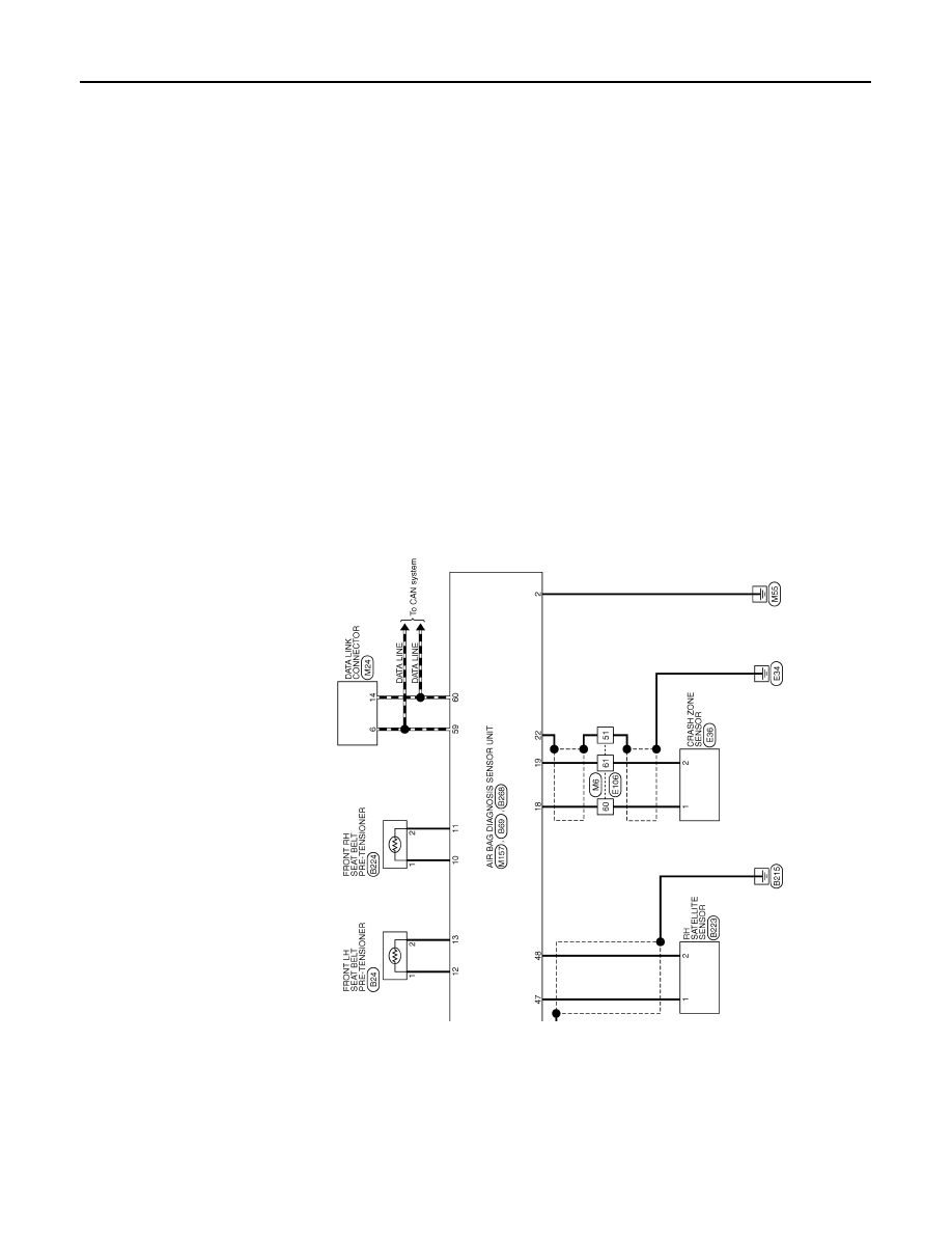
SRC-12
< ECU DIAGNOSIS INFORMATION >
DIAGNOSIS SENSOR UNIT
JRHWC0359GB
|
|
|
содержание .. 297 298 299 300 ..
SRC-12 < ECU DIAGNOSIS INFORMATION > DIAGNOSIS SENSOR UNIT JRHWC0359GB |