содержание .. 291 292 293 294 ..
Nissan GT-R. Manual - part 293
SPIRAL CABLE
SR-15
< REMOVAL AND INSTALLATION >
C
D
E
F
G
I
J
K
L
M
A
B
SR
N
O
P
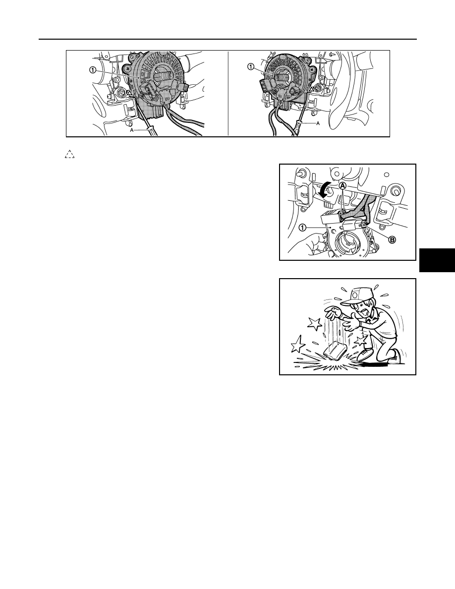
6.
Remove the spiral cable (1) fixing pawls with remover tool (A).
7.
Pull the spiral cable (1), and then disconnect the spiral cable
harness connectors (A) and steering angle sensor harness con-
nector (B).
8.
Remove the spiral cable.
CAUTION:
• Never impact the spiral cable.
• Replace the spiral cable if it is dropped or sustains an impact.
• Never disassemble the spiral cable.
• Never apply lubricant to the spiral cable.
• Never allow oil, grease, detergent, or water to come in contact with the spiral cable.
INSTALLATION
: Pawl
JMHIA0717ZZ
JMHIA0718ZZ
JMHIA0009ZZ