Nissan GT-R. Manual - part 289


  Главная      Nissan     Nissan GT-R (2007-2014 year) - Service Manual


поиск по сайту            


содержание   ..  287  288  289  290   ..


Nissan GT-R. Manual - part 289


SEC-38

< PRECAUTION >

[INTELLIGENT KEY SYSTEM]

PRECAUTIONS

4.

Perform the necessary repair operation.

5.

When the repair work is completed, re-connect both battery cables. With the brake pedal released, turn
the ignition switch from ACC position to ON position, then to LOCK position. (The steering wheel will lock
when the ignition switch is turned to LOCK position.)

6.

Perform self-diagnosis check of all control units using CONSULT.

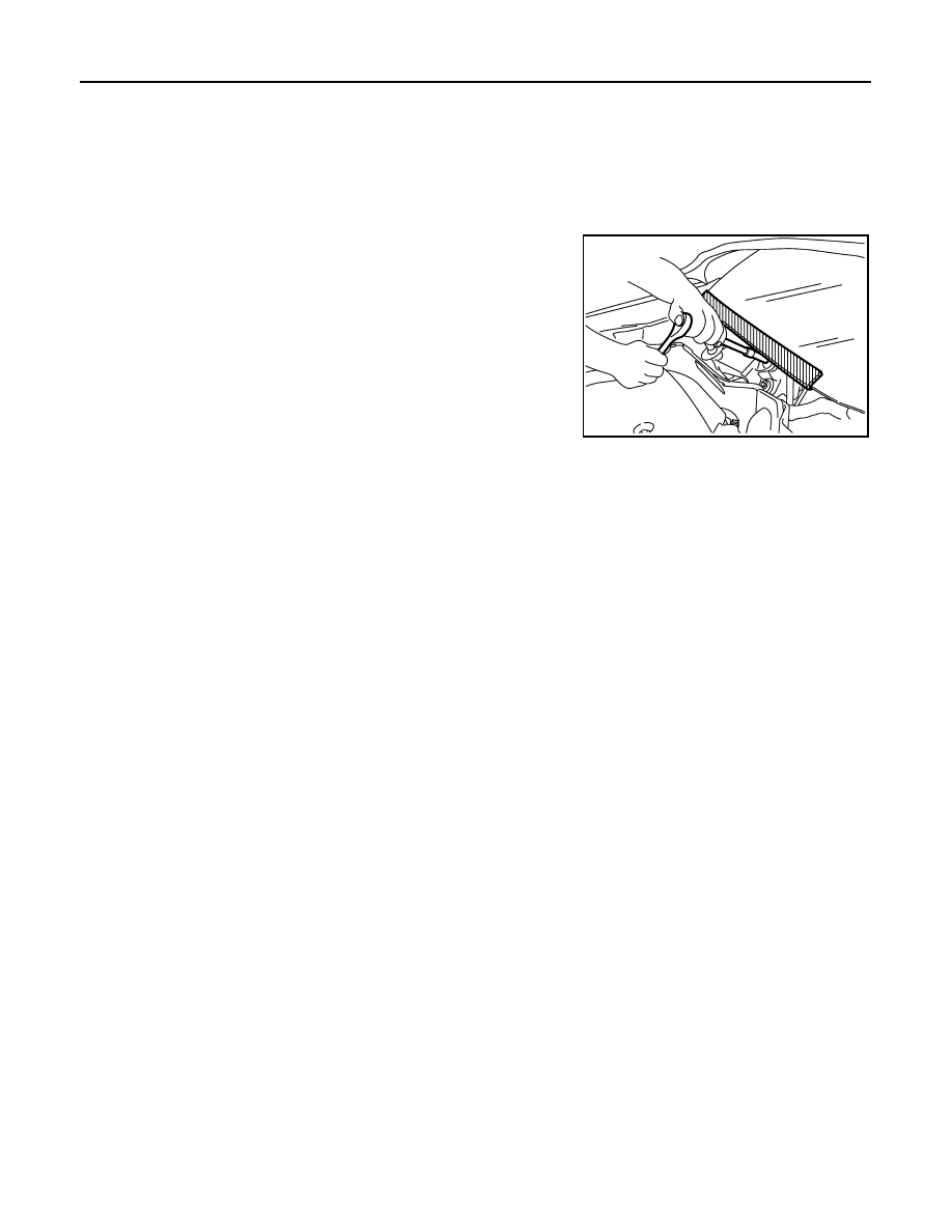
Precaution for Procedure without Cowl Top Cover

INFOID:0000000009163804

When performing the procedure after removing cowl top cover, cover
the lower end of windshield with urethane, etc to prevent damage to
windshield.

Precaution for Battery Service

INFOID:0000000009163805

Before disconnecting the battery, lower both the driver and passenger windows. This will prevent any interfer-
ence between the window edge and the vehicle when the door is opened/closed. During normal operation, the
window slightly raises and lowers automatically to prevent any window to vehicle interference. The automatic
window function will not work with the battery disconnected.

PIIB3706J

SECURITY INDICATOR LAMP

SEC-39

< REMOVAL AND INSTALLATION >

[INTELLIGENT KEY SYSTEM]

C

D

E

F

G

H

I

J

L

M

A

B

SEC

N

O

P

REMOVAL AND INSTALLATION

SECURITY INDICATOR LAMP

Exploded View

INFOID:0000000009163806

Removal and Installation

INFOID:0000000009163807

REMOVAL

Disengage pawls with remover tool (A) and pull up the security indicator lamp (1).

INSTALLATION

Install in the reverse order of removal.

1.

Security indicator lamp

JMKIA2993ZZ

: Pawl

JMKIA2994ZZ

SR-1

RESTRAINTS

C

D

E

F

G

I

J

K

L

M

SECTION 

SR

A

B

SR

N

O

P

CONTENTS

SRS AIRBAG

PRECAUTION ...............................................

2

PRECAUTIONS ...................................................

2

Precaution for Supplemental Restraint System 
(SRS) "AIR BAG" and "SEAT BELT PRE-TEN-
SIONER" .................................................................
..

2

Precautions Necessary for Steering Wheel Rota-
tion After Battery Disconnection  ..............................
..

2

Precaution for Battery Service  ..................................

3

Service ......................................................................

3

Occupant Classification System ..............................

3

PREPARATION ............................................

4

PREPARATION ...................................................

4

Commercial Service Tools  ........................................

4

BASIC INSPECTION  ....................................

5

COLLISION DIAGNOSIS  ....................................

5

FOR FRONTAL COLLISION  .......................................

5

FOR FRONTAL COLLISION : When SRS is acti-
vated in a collision ...................................................
..

5

FOR FRONTAL COLLISION : When SRS is not 
activated in a collision  .............................................
..

6

FOR SIDE AND ROLLOVER COLLISION  ..................

7

FOR SIDE AND ROLLOVER COLLISION : When 
SRS is activated in a collision  .................................
..

7

FOR SIDE AND ROLLOVER COLLISION : When 
SRS is not activated in a collision  ...........................
..

8

REMOVAL AND INSTALLATION  ...............

11

DRIVER AIR BAG MODULE  ............................

11

Exploded View .........................................................

11

Removal and Installation  .........................................

11

SPIRAL CABLE  ................................................

14

Exploded View .........................................................

14

Removal and Installation  .........................................

14

PASSENGER AIR BAG MODULE  ...................

17

Exploded View .........................................................

17

Removal and Installation  .........................................

17

CURTAIN AIR BAG MODULE  ..........................

19

Exploded View .........................................................

19

Removal and Installation  .........................................

19

CRASH ZONE SENSOR ...................................

21

Exploded View .........................................................

21

Removal and Installation  .........................................

21

SATELLITE SENSOR  .......................................

23

Exploded View .........................................................

23

Removal and Installation  .........................................

23

DIAGNOSIS SENSOR UNIT  .............................

25

Exploded View .........................................................

25

Removal and Installation  .........................................

25

OCCUPANT CLASSIFICATION SYSTEM 
CONTROL UNIT ................................................

27

Removal and Installation  .........................................

27

SR-2

< PRECAUTION >

PRECAUTIONS

PRECAUTION

PRECAUTIONS

Precaution for Supplemental Restraint System (SRS) "AIR BAG" and "SEAT BELT 
PRE-TENSIONER"

INFOID:0000000009161517

The Supplemental Restraint System such as “AIR BAG” and “SEAT BELT PRE-TENSIONER”, used along
with a front seat belt, helps to reduce the risk or severity of injury to the driver and front passenger for certain
types of collision. This system includes seat belt switch inputs and dual stage front air bag modules. The SRS
system uses the seat belt switches to determine the front air bag deployment, and may only deploy one front
air bag, depending on the severity of a collision and whether the front occupants are belted or unbelted.
Information necessary to service the system safely is included in the “SRS AIR BAG” and “SEAT BELT” of this
Service Manual.

WARNING:

Always observe the following items for preventing accidental activation.
• To avoid rendering the SRS inoperative, which could increase the risk of personal injury or death in

the event of a collision that would result in air bag inflation, all maintenance must be performed by
an authorized NISSAN/INFINITI dealer.

• Improper maintenance, including incorrect removal and installation of the SRS, can lead to personal

injury caused by unintentional activation of the system. For removal of Spiral Cable and Air Bag
Module, see “SRS AIR BAG”.

• Never use electrical test equipment on any circuit related to the SRS unless instructed to in this Ser-

vice Manual. SRS wiring harnesses can be identified by yellow and/or orange harnesses or harness
connectors.

PRECAUTIONS WHEN USING POWER TOOLS (AIR OR ELECTRIC) AND HAMMERS

WARNING:

Always observe the following items for preventing accidental activation.
• When working near the Air Bag Diagnosis Sensor Unit or other Air Bag System sensors with the

ignition ON or engine running, never use air or electric power tools or strike near the sensor(s) with
a hammer. Heavy vibration could activate the sensor(s) and deploy the air bag(s), possibly causing
serious injury.

• When using air or electric power tools or hammers, always switch the ignition OFF, disconnect the

battery, and wait at least 3 minutes before performing any service.

Precautions Necessary for Steering Wheel Rotation After Battery Disconnection

INFOID:0000000009161518

CAUTION:

Comply with the following cautions to prevent any error and malfunction.
• Before removing and installing any control units, first turn the ignition switch to the LOCK position,

then disconnect both battery cables.

• After finishing work, confirm that all control unit connectors are connected properly, then re-connect

both battery cables.

• Always use CONSULT to perform self-diagnosis as a part of each function inspection after finishing

work. If a DTC is detected, perform trouble diagnosis according to self-diagnosis results.

For vehicle with steering lock unit, if the battery is disconnected or discharged, the steering wheel will lock and
cannot be turned.
If turning the steering wheel is required with the battery disconnected or discharged, follow the operation pro-
cedure below before starting the repair operation.

OPERATION PROCEDURE

1.

Connect both battery cables.
NOTE:
Supply power using jumper cables if battery is discharged.

2.

Turn the ignition switch to ACC position.
(At this time, the steering lock will be released.)

3.

Disconnect both battery cables. The steering lock will remain released with both battery cables discon-
nected and the steering wheel can be turned.


содержание   ..  287  288  289  290   ..