содержание .. 169 170 171 172 ..
Nissan GT-R. Manual - part 171
ILLUMINATION CONTROL SYSTEM
INL-9
< SYSTEM DESCRIPTION >
C
D
E
F
G
H
I
J
K
M
A
B
INL
N
O
P
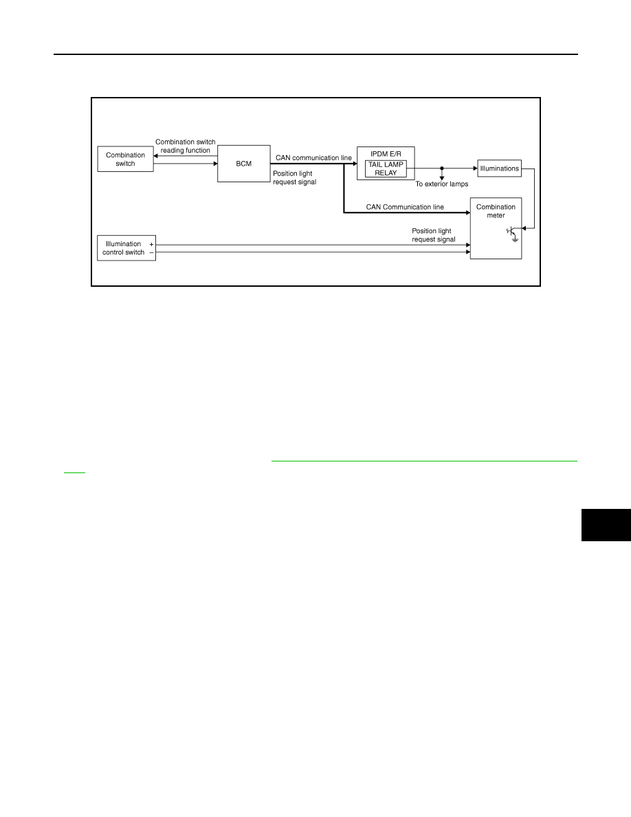
ILLUMINATION CONTROL SYSTEM
System Diagram
INFOID:0000000009161893
System Description
INFOID:0000000009161894
OUTLINE
Each illumination lamp is controlled by each function of BCM, IPDM E/R and combination meter.
Control by BCM
• Combination switch reading function
• Headlamp control function
Control by IPDM E/R
• Relay control function
Control by combination meter
• Meter illumination control function (Refer to
MWI-24, "METER ILLUMINATION CONTROL : System Descrip-
ILLUMINATION CONTROL
• BCM detects the combination switch condition by the combination switch reading function.
• BCM transmits position light request signal to IPDM E/R and combination meter according to tail lamp ON
condition.
Tail lamp ON condition
- Lighting switch 1ST
- Lighting switch 2ND
• IPDM E/R turns the integrated tail lamp relay ON according to position light request signal. It provides the
power supply to each illumination lamp.
• Combination meter enters in the nighttime mode according to position light request signal. Under the night-
time mode the combination meter controls the illuminance by controlling the each illumination lamp (ground
side).
JPLIA0855GB