содержание .. 165 166 167 168 ..
Nissan GT-R. Manual - part 167
HAC-30
< REMOVAL AND INSTALLATION >
[AUTOMATIC AIR CONDITIONER]
SUNLOAD SENSOR
SUNLOAD SENSOR
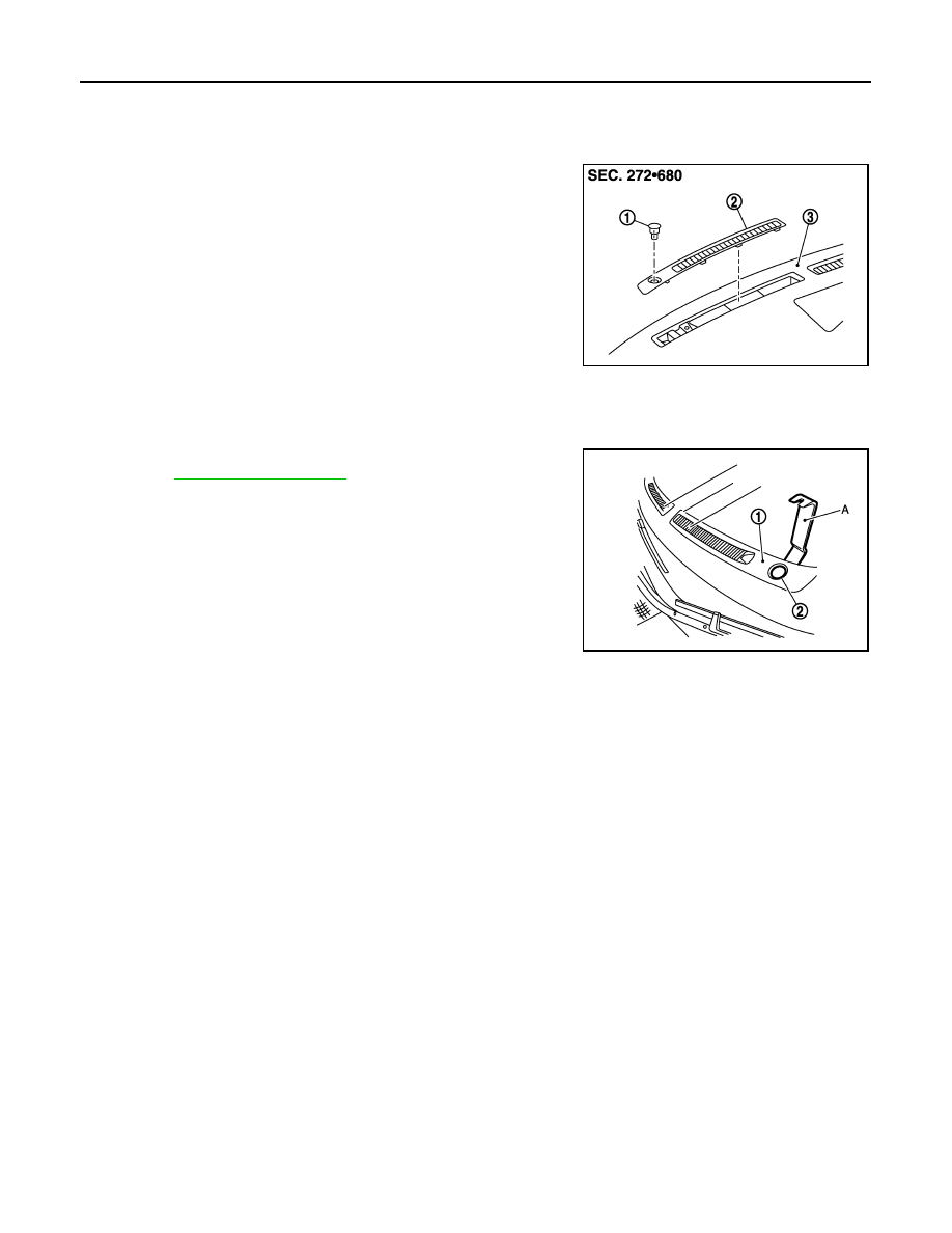
Exploded View
INFOID:0000000009164059
Removal and Installation
INFOID:0000000009164060
REMOVAL
1.
Remove front defroster grille (left) (1), using remover tools (A).
Refer to
.
2.
Disconnect sunload sensor connector, and then remove sunload
sensor (2).
INSTALLATION
Installation is basically the reverse order of removal.
1.
Sunload sensor
2.
Front defroster grille (left)
3.
Instrument panel assembly
NNIIA0136ZZ
NNIIA0137ZZ