содержание .. 138 139 140 141 ..
Nissan GT-R. Manual - part 140
GI-32
< PRECAUTION >
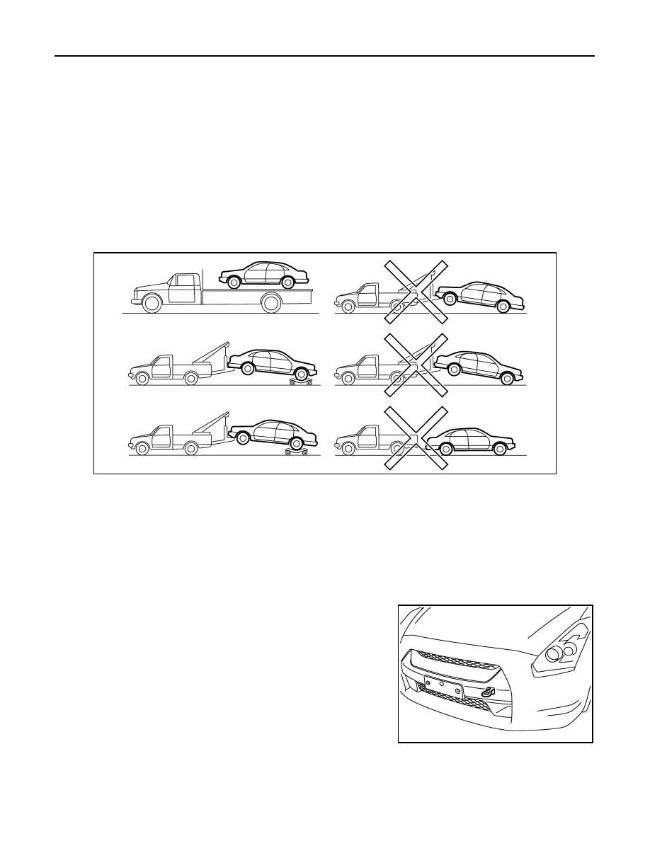
TOW TRUCK TOWING
TOW TRUCK TOWING
Tow Truck Towing
INFOID:0000000009161505
CAUTION:
• All applicable state or Provincial (in Canada) laws and local laws regarding the towing operation
must be obeyed.
• It is necessary to use proper towing equipment to avoid possible damage to the vehicle during tow-
ing operation. Towing is in accordance with Towing Procedure Manual at dealer.
• Always attach safety chains before towing.
• When towing, check that the transmission, steering system and powertrain are in good order. If any
unit is damaged, dollies must be used.
• Never tow an automatic transmission model from the rear (that is backward) with four wheels on the
ground. This may cause serious and expensive damage to the transmission.
AWD MODELS
NISSAN recommends that vehicle be towed with the driving (rear) wheels off the ground or that a dolly be
used as illustrated.
CAUTION:
Never tow AWD models with any of the wheels on the ground as this may cause serious and expen-
sive damage to the powertrain.
Vehicle Recovery (Freeing a Stuck Vehicle)
INFOID:0000000009161506
FRONT
Securely install the vehicle recovery hook stored with jacking tools.
Check that the hook is properly secured in the stored place after use.
WARNING:
• Stand clear of a stuck vehicle.
• Never spin your tires at high speed. This could cause them to
explode and result in serious injury. Parts of your vehicle
could also overheat and be damaged.
CAUTION:
• Tow chains or cables must be attached only to the vehicle
recovery hooks or main structural members of the vehicle.
Otherwise, the vehicle body will be damaged.
• Never use the vehicle tie downs to free a vehicle stuck in
sand, snow, mud, etc. Never tow the vehicle using the vehicle tie downs or recovery hooks.
• Always pull the cable straight out from the front of the vehicle. Never pull on the hook at an angle.
• Pulling devices should be routed so they never touch any part of the suspension, steering, brake or
cooling systems.
PIIB6403E
NNAIB0002ZZ