Nissan GT-R. Manual - part 132


  Главная      Nissan     Nissan GT-R (2007-2014 year) - Service Manual


поиск по сайту            


содержание   ..  130  131  132  133   ..


Nissan GT-R. Manual - part 132


SERVICE DATA AND SPECIFICATIONS (SDS)

FSU-17

< SERVICE DATA AND SPECIFICATIONS (SDS) 

C

D

F

G

H

I

J

K

L

M

A

B

FSU

N

O

P

- Always adjust to toe-in. If the wheels change to toe-out, tire partial wear is accelerated and local heating may

be accelerated in the inner side of tires.

- Always adjust toe-in to 1.5 mm (0.059 in) or less because too much toe-in may promote local heat genera-

tion.

- For the above reasons, always adjust to toe-in for the vehicle of a customer who drives on a racetrack.
- Engaging in performance driving on a racetrack and ultra-high-speed driving, be sure to adjust toe-in to 1.5

mm (0.059 in) or less. If used beyond this range, it is not covered by the warranty.

• Insufficient negative camber during hard cornering on a racetrack may result in tire wear. Therefore, recom-

mend the customer to adjust negative camber angle in the negative direction when driving on a racetrack.
[To avoid uneven wear, recommend the customer to have the camber angle aligned in the positive direction
at an inspection after performance driving (at customer's expense).]

• Wheel alignment can be changed in process of time and mileage, as suspension parts do not adjust to each

other up to the mileage of about 1,000 miles or 2,000 km.

• Remarks for up to the mileage of 1,000 miles or 2,000 km
- Toe angle of one-side wheel: See reference value.
• Each part of the suspension may not conform during a normal driving because of the adoption of a hard rate

coil spring and a high damping shock absorber.

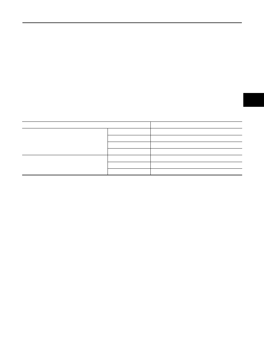
CASTER, KINGPIN INCLINATION

Measure value under unladen

*

 conditions.

*: Fuel, engine coolant and lubricant are full. Jack, hand tools and mats are in designated positions.

• Wheel alignment can be changed in process of time and mileage, as suspension parts do not adjust to each

other up to the mileage of about 1,000 miles or 2,000 km.

• Each part of the suspension may not conform during a normal driving because of the adoption of a hard rate

coil spring and a high damping shock absorber.

Item

Standard

Caster
Degree minute (Decimal degree)

Minimum

5

°

 45

 (5.75

°

)

Nominal

6

°

 05

 (6.08

°

)

Maximum

6

°

 45

 (6.75

°

)

Left and right difference

0

°

 30

 (0.50

°

) or less

Kingpin inclination
Degree minute (Decimal degree)

Minimum

9

°

 30

 (9.50

°

)

Nominal

9

°

 40

 (9.67

°

)

Maximum

9

°

 50

 (9.83

°

)

GI-1

GENERAL INFORMATION

C

D

E

F

G

H

I

J

K

L

M

B

GI

SECTION 

GI

N

O

P

CONTENTS

GENERAL INFORMATION

HOW TO USE THIS MANUAL ......................

3

HOW TO USE THIS MANUAL  ............................

3

Description ................................................................

3

Terms ........................................................................

3

Units ..........................................................................

3

Contents ....................................................................

3

Relation between Illustrations and Descriptions  .......

4

Components ..............................................................

4

HOW TO FOLLOW TROUBLE DIAGNOSES .....

6

Description ................................................................

6

How to Follow Test Groups in Trouble Diagnosis ......

6

Key to Symbols Signifying Measurements or Pro-
cedures ...................................................................
..

7

HOW TO READ WIRING DIAGRAMS  ................

9

Connector Symbols ...................................................

9

Sample/Wiring Diagram -Example-  .........................

10

Connector Information .............................................

12

ABBREVIATIONS ..............................................

14

Abbreviation List ......................................................

14

TIGHTENING TORQUE OF STANDARD 
BOLTS ................................................................

15

Description ..............................................................

15

Tightening Torque Table (New Standard Includ-
ed) ...........................................................................

15

RECOMMENDED CHEMICAL PRODUCTS 
AND SEALANTS ................................................

18

Recommended Chemical Products and Sealants 

....

18

VEHICLE INFORMATION ............................

19

IDENTIFICATION INFORMATION  .....................

19

Model Variation  .......................................................

19

Information About Identification or Model Code  ......

19

Dimensions .............................................................

21

Wheels & Tires ........................................................

21

PRECAUTION ..............................................

22

PRECAUTIONS .................................................

22

Description ...............................................................

22

Precaution for Supplemental Restraint System 
(SRS) "AIR BAG" and "SEAT BELT PRE-TEN-
SIONER" .................................................................

22

Precautions For Xenon Headlamp Service  .............

22

Precautions Necessary for Steering Wheel Rota-
tion After Battery Disconnection  ..............................

23

Precaution for Battery Service .................................

23

Precaution for Procedure without Cowl Top Cover ....

23

Cautions in Removing Battery Terminal and AV 
Control Unit (Models with AV Control Unit)  .............

23

Aluminum Die-Casting Parts Handling  ....................

24

General Precautions ................................................

24

Three Way Catalyst  .................................................

26

Multiport Fuel Injection System or Engine Control 
System .....................................................................

26

Precaution for Turbocharger ....................................

26

Hoses ......................................................................

26

Engine Oils  ..............................................................

27

Air Conditioning  .......................................................

28

Service Notice or Precautions for Front Propeller 
Shaft (GT-R certified NISSAN dealer)  .....................

28

Service notice or Precautions for Main Propeller 
Shaft (GT-R certified NISSAN dealer)  .....................

28

Fuel ..........................................................................

28

LIFTING POINT .................................................

30

Commercial Service Tools .......................................

30

Garage Jack and Safety Stand and 2-Pole Lift  .......

30

Board-On Lift  ...........................................................

30

TOW TRUCK TOWING  .....................................

32

Tow Truck Towing  ...................................................

32

Vehicle Recovery (Freeing a Stuck Vehicle)  ...........

32

BASIC INSPECTION  ...................................

34

HOW TO USE THIS MANUAL

GI-3

< HOW TO USE THIS MANUAL >

C

D

E

F

G

H

I

J

K

L

M

B

GI

N

O

P

HOW TO USE THIS MANUAL

HOW TO USE THIS MANUAL

Description

INFOID:0000000009161464

This volume explains “Removal, Disassembly, Installation, Inspection and Adjustment” and “Trouble Diag-
noses”.

Terms

INFOID:0000000009161465

• The captions WARNING and CAUTION warn you of steps that must be followed to prevent personal injury

and/or damage to some part of the vehicle.
WARNING indicates the possibility of personal injury if instructions are not followed.
CAUTION indicates the possibility of component damage if instructions are not followed.
BOLD TYPED STATEMENTS except WARNING and CAUTION give you helpful information.
Standard value: Tolerance at inspection and adjustment.
Limit value: The maximum or minimum limit value that should not be exceeded at inspection and adjust-
ment.

Units

INFOID:0000000009161466

• The UNITS given in this manual are primarily expressed as the SI UNIT (International System of Unit), and

alternatively expressed in the metric system and in the yard/pound system.
Also with regard to tightening torque of bolts and nuts, there are descriptions both about range and about the
standard tightening torque.

“Example”
Range

Standard

Contents

INFOID:0000000009161467

• A QUICK REFERENCE INDEX, a black tab (e.g. 

) is provided on the first page. You can quickly find the

first page of each section by matching it to the section's black tab.

• THE CONTENTS are listed on the first page of each section.
• THE TITLE is indicated on the upper portion of each page and shows the part or system.
• THE PAGE NUMBER of each section consists of two or three letters which designate the particular section

and a number (e.g. “BR-5”).

• THE SMALL ILLUSTRATIONS show the important steps such as inspection, use of special tools, knacks of

work and hidden or tricky steps which are not shown in the previous large illustrations.
Assembly, inspection and adjustment procedures for the complicated units such as the automatic transaxle
or transmission, etc. are presented in a step-by-step format where necessary.

Outer Socket Lock Nut

: 59 - 78 N·m (6.0 - 8.0 kg-m, 43 - 58 ft-lb)

Drive Shaft Installation Bolt

: 44.3 N·m (4.5 kg-m, 33 ft-lb)


содержание   ..  130  131  132  133   ..