Nissan GT-R. Manual - part 93


  Главная      Nissan     Nissan GT-R (2007-2014 year) - Service Manual


поиск по сайту            


содержание   ..  91  92  93  94   ..


Nissan GT-R. Manual - part 93


EM-20

< REMOVAL AND INSTALLATION >

INTAKE MANIFOLD COLLECTOR
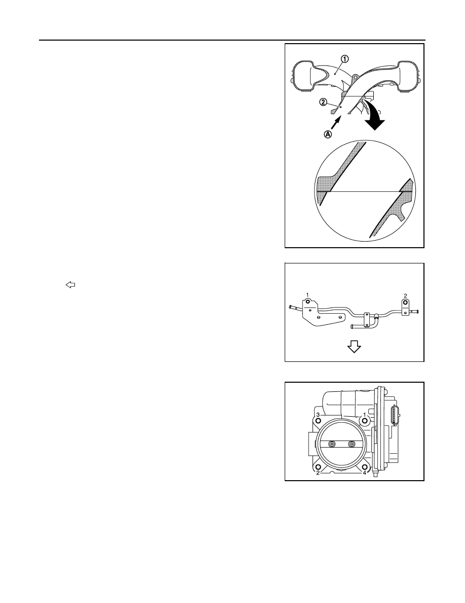
2.

Temporarily assemble intake manifold collector (1) and intake
manifold (2).

3.

Check an exact location that the intake manifold collector port
locates inside the intake manifold port and mark each part.
Refer to the arrow (A) shown in the figure to check the location.

4.

After another disassembly, install the parts, aligning with the
marks put before the temporary assembly.

CAUTION:

Tighten mounting bolts with care to avoid misalignment in
the intake manifold collector and intake manifold.

EVAP Tube (front)

• Tighten mounting bolts in numerical order as shown in the figure.

Electric Throttle Control Actuator

• Tighten bolts in numerical order as shown in the figure.

NOTE:
• The figure shows the electric throttle control actuator (bank 2)

viewed from the air duct side. 

• Viewed from the air duct side, the order of tightening mounting

bolts of electric throttle control actuator (bank 2) is the same as
that of the electric throttle control actuator (bank 1).

• Perform the “Throttle Valve Closed Position Learning” when har-

ness connector of electric throttle control actuator is discon-
nected. (This work is recommended to be performed by GT-R
certified NISSAN dealer.)

• Perform the “Idle Air Volume Learning” and “Throttle Valve

Closed Position Learning” when electric throttle control actuator is replaced. (This work is recommended to
be performed by GT-R certified NISSAN dealer.) 

NNBIA0205ZZ

: Engine front

NNBIA0041ZZ

NNBIA0230ZZ

INTAKE MANIFOLD

EM-21

< REMOVAL AND INSTALLATION >

C

D

E

F

G

H

I

J

K

L

M

A

EM

N

P

O

INTAKE MANIFOLD

Exploded View

INFOID:0000000009162840

Removal and Installation

INFOID:0000000009162841

REMOVAL

1.

Remove intake manifold collector. Refer to 

EM-17, "Exploded View"

.

CAUTION:

Mark the parts with paint in advance of the reinstallation to prevent misalignment between the
intake manifold collector and intake manifold.

2.

Loosen pressure regulator and fuel hose assembly mounting bolt. Refer to 

EM-23, "Exploded View"

.

3.

Disconnect harness connector from fuel tube.

4.

Remove intake manifold.
• Loosen mounting bolts in reverse order as shown in the figure

with power tool.

CAUTION:

• Mark the parts with paint in advance of the reinstallation

to prevent misalignment between the intake manifold and
cylinder head.

• Cover engine openings to avoid entry of foreign materi-

als.

5.

Remove gaskets.

INSTALLATION

Note the following, and install in the reverse order of removal.

Intake Manifold

1.

Intake manifold

2.

Gasket

: Engine front

Refer to 

GI-4, "Components"

 for symbols in the figure.

NNBIA0012GB

: Engine front

NNBIA0013ZZ

EM-22

< REMOVAL AND INSTALLATION >

INTAKE MANIFOLD

• Tighten mounting bolts in numerical order as shown in the figure.

•  Refer to the figure to check the installation direction of the intake

manifold.

CAUTION:

• Install each part according to the marks put before removal.
• Tighten mounting bolts with care to avoid misalignment in the

intake manifold.

• After replacing an intake manifold, be sure to adjust the position as instructed below.
• Check an exact location that the intake manifold port locates inside

the cylinder head port and mark each part. Refer to the arrow (A)
shown in the figure to check the location.

CAUTION:

Tighten mounting bolts with care to avoid misalignment in the
intake manifold.

: Engine front

NNBIA0013ZZ

1 : Intake manifold

2 : Cylinder head

NNBIA0204ZZ

FUEL INJECTOR AND FUEL TUBE

EM-23

< REMOVAL AND INSTALLATION >

C

D

E

F

G

H

I

J

K

L

M

A

EM

N

P

O

FUEL INJECTOR AND FUEL TUBE

Exploded View

INFOID:0000000009162843

CAUTION:

Never remove or disassemble parts unless instructed as shown in the figure.

1.

Fuel feed hose (with damper)

2.

Fuel return hose (with damper)

3.

Fuel tube

4.

O-ring (black)

5.

Clip

6.

Fuel injector

7.

O-ring (green)

8.

O-ring

9.

Fuel damper

10. Fuel damper cap

11. O-ring

12. Vacuum hose

13. Fuel hose (with pressure regulator)

A.

To centralized under-floor piping

B.

This work is recommended to be per-
formed by GT-R certified NISSAN 
dealer.

C.

To intake manifold collector

Refer to 

GI-4, "Components"

 for symbols in the figure.

NNBIA0036GB


содержание   ..  91  92  93  94   ..