Nissan GT-R. Manual - part 87


  Главная      Nissan     Nissan GT-R (2007-2014 year) - Service Manual


поиск по сайту            


содержание   ..  85  86  87  88   ..


Nissan GT-R. Manual - part 87


EC-22

< PRECAUTION >

[VR38]

PRECAUTIONS

• After performing each TROUBLE DIAGNOSIS, perform DTC

Confirmation Procedure or Component Function Check.
The DTC should not be displayed in the DTC Confirmation
Procedure if the repair is completed. The Component Func-
tion Check should be a good result if the repair is completed.

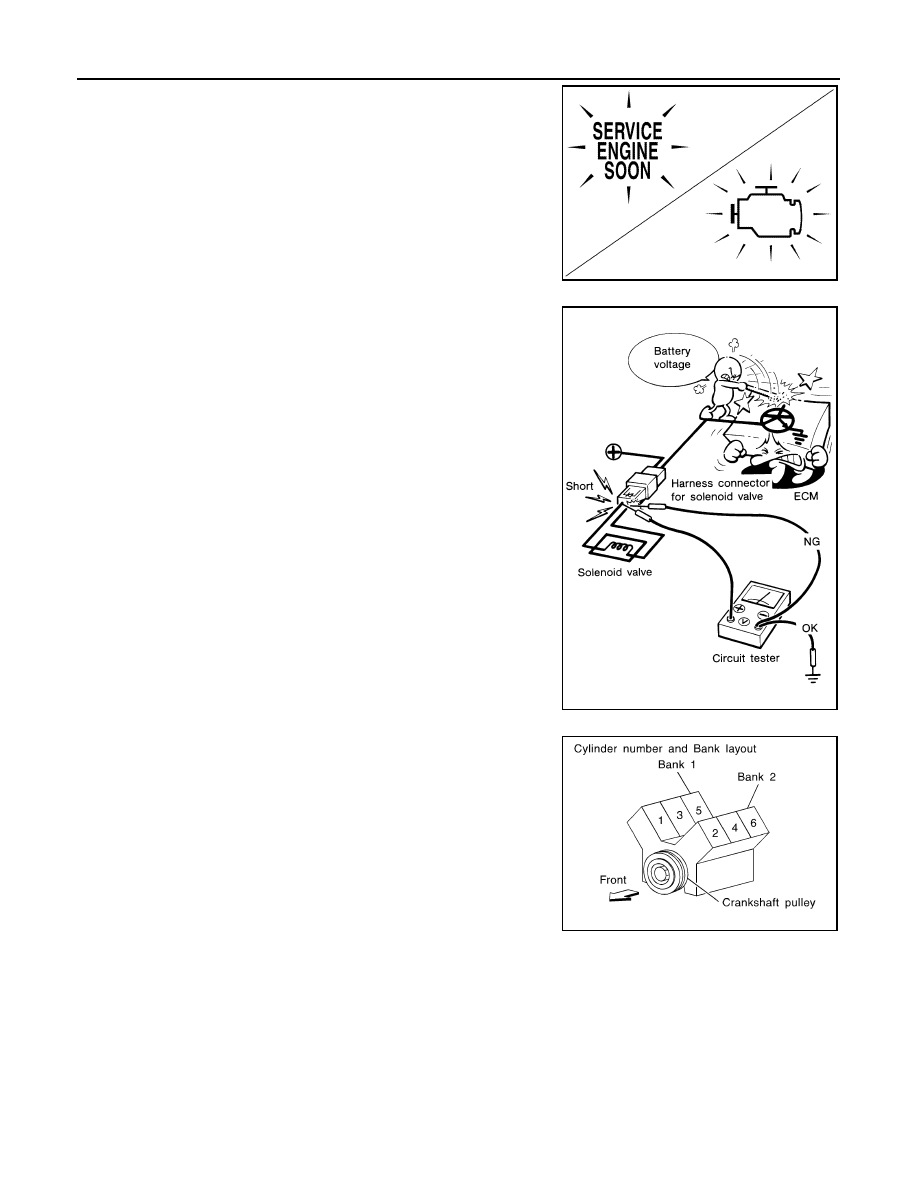
• When measuring ECM signals with a circuit tester, never allow

the two tester probes to contact.
Accidental contact of probes will cause a short circuit and
damage the ECM power transistor.

• B1 indicates the bank 1, B2 indicates the bank 2 as shown in

the figure.

• Never operate fuel pump when there is no fuel in lines.
• Tighten fuel hose clamps to the specified torque.

JSBIA1315ZZ

SEF348N

SEC893C

PRECAUTIONS

EC-23

< PRECAUTION >

[VR38]

C

D

E

F

G

H

I

J

K

L

M

A

EC

N

P

O

• Never depress accelerator pedal when starting.
• Immediately after starting, never rev up engine unnecessarily.
• Never rev up engine just prior to shutdown.

• When installing C.B. ham radio or a mobile phone, be sure to

observe the following as it may adversely affect electronic
control systems depending on installation location.

Keep the antenna as far as possible from the electronic con-

trol units.

Keep the antenna feeder line more than 0.2 m (0.7 ft) away

from the harness of electronic controls.
Never let them run parallel for a long distance.

Adjust the antenna and feeder line so that the standing-wave

ratio can be kept smaller.

Be sure to ground the radio to vehicle body.

SEF709Y

SEF708Y

EC-24

< PERIODIC MAINTENANCE >

[VR38]

EVAP LEAK CHECK

PERIODIC MAINTENANCE

EVAP LEAK CHECK

Inspection

INFOID:0000000009161045

CAUTION:

• Do not use compressed air or a high pressure pump.
• Do not exceed 4.12 kPa (0.041 bar, 0.042 kg/cm

2

, 0.6 psi) of pressure in EVAP system.

NOTE:
• Do not start engine.
• Improper installation of EVAP service port adapter (commercial service tool) to the EVAP service port may

cause a leak.

 WITH CONSULT

1.

To locate the EVAP leak, install EVAP service port adapter (com-
mercial service tool) and pressure pump to EVAP service port.

2.

Turn ignition switch ON.

3.

Select the “EVAP SYSTEM CLOSE” of “WORK SUPPORT”
mode with CONSULT.

4.

Touch “START”. A bar graph (Pressure indicating display) will
appear on the screen.

5.

Apply positive pressure to the EVAP system until the pressure
indicator reaches the middle of the bar graph.

6.

Remove EVAP service port adapter (commercial service tool)
and hose with pressure pump.

7.

Locate the leak using a leak detector (commercial service tool).

 WITHOUT CONSULT

1.

To locate the EVAP leak, install EVAP service port adapter (com-
mercial service tool) and pressure pump to EVAP service port.

2.

Apply battery voltage between the terminals of EVAP canister
vent control valve to make a closed EVAP system.

3.

To locate the leak, deliver positive pressure to the EVAP system
until pressure gauge points reach 1.38 to 2.76 kPa (0.013 –
0.027 bar, 0.014 – 0.028 kg/cm

2

, 0.2 – 0.4 psi).

4.

Remove EVAP service port adapter (commercial service tool)
and hose with pressure pump.

SEF462UA

SEF200U

SEF462UA

EVAP LEAK CHECK

EC-25

< PERIODIC MAINTENANCE >

[VR38]

C

D

E

F

G

H

I

J

K

L

M

A

EC

N

P

O

5.

Locate the leak using a leak detector (commercial service tool).

SEF200U


содержание   ..  85  86  87  88   ..