содержание .. 84 85 86 87 ..
Nissan GT-R. Manual - part 86
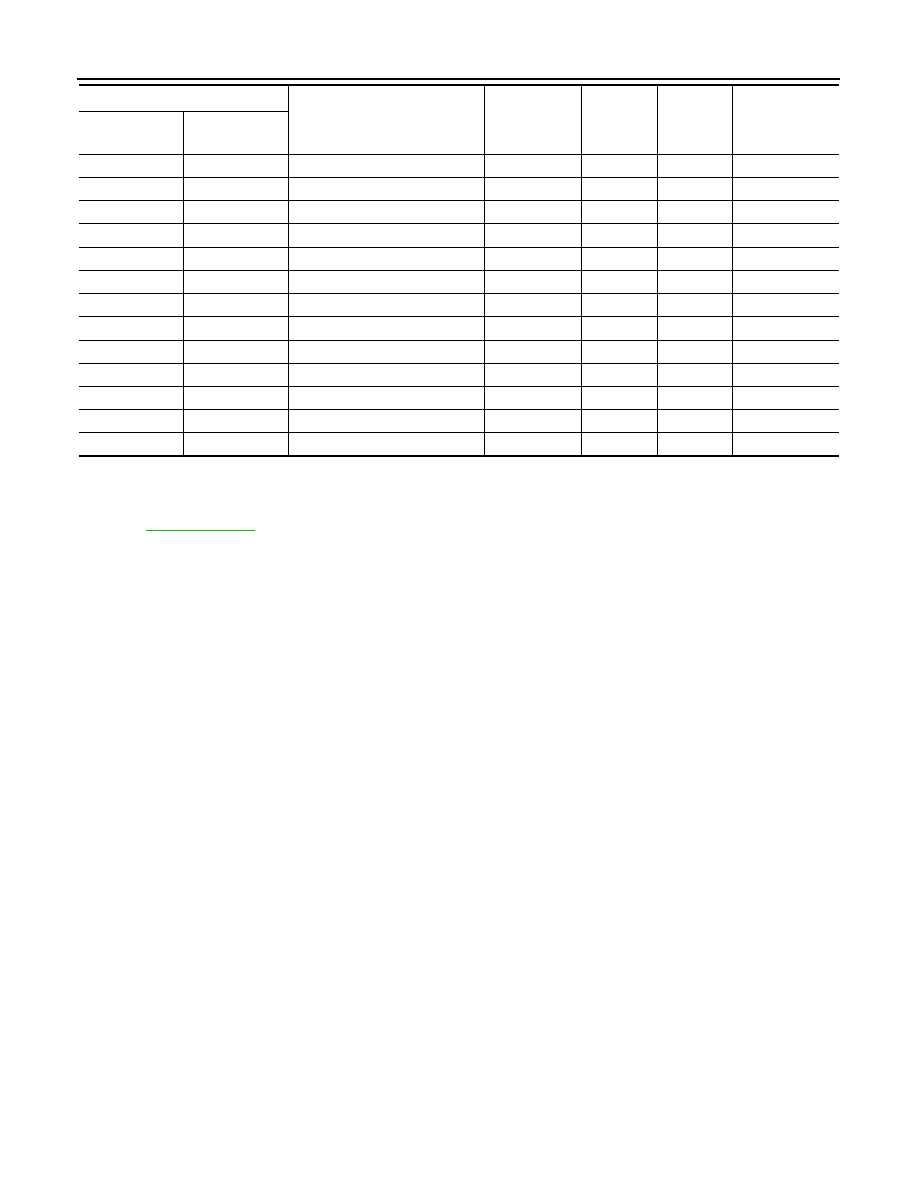
EC-18
< ECU DIAGNOSIS INFORMATION >
[VR38]
ECM
*1: 1st trip DTC No. is the same as DTC No.
*2: This number is prescribed by SAE J2012/ISO 15031-6.
*3: In Diagnostic Test Mode II (Self-diagnostic results), this number is controlled by NISSAN.
*4: Refer to
, “HOW TO ERASE PERMANENT DTC”.
*5: The troubleshooting for this DTC needs CONSULT.
*6: When the ECM is in the mode that displays SRT status, MIL may blink. For the details, refer to “How to Display SRT Status”.
*7: SRT code will not be set if the self-diagnostic result is NG.
*8: When the fail-safe operations for both self-diagnoses occur, the MIL illuminates.
P2122
2122
APP SEN 1/CIRC
—
1
×
B
P2123
2123
APP SEN 1/CIRC
—
1
×
B
P2127
2127
APP SEN 2/CIRC
—
1
×
B
P2128
2128
APP SEN 2/CIRC
—
1
×
B
P2132
2132
TP SEN 1/CIRC-B2
—
1
×
B
P2133
2133
TP SEN 1/CIRC-B2
—
1
×
B
P2135
2135
TP SENSOR-B1
—
1
×
B
P2138
2138
APP SENSOR
—
1
×
B
P2263
2263
TC SYSTEM-B1
—
2
—
—
P2432
2432
SNDRY MAS A/F SE
—
2
×
B
P2433
2433
SNDRY MAS A/F SE
—
2
×
B
P2440
2440
AIR CUT S/V-B1
×
1 or 2
×
B
P2442
2442
AIR CUT S/V-B2
×
2
×
B
DTC*
1
Items
(CONSULT screen terms)
SRT code
Trip
MIL
Permanent DTC
group*
4
CONSULT
GST*
2
ECM*
3