содержание .. 23 24 25 26 ..
Nissan GT-R. Manual - part 25
AV
REAR VIEW CAMERA
AV-95
< REMOVAL AND INSTALLATION >
[BASE AUDIO WITH NAVIGATION]
C
D
E
F
G
H
I
J
K
L
M
B
A
O
P
REAR VIEW CAMERA
Exploded View
INFOID:0000000009163325
REMOVAL
.
DISASSEMBLY
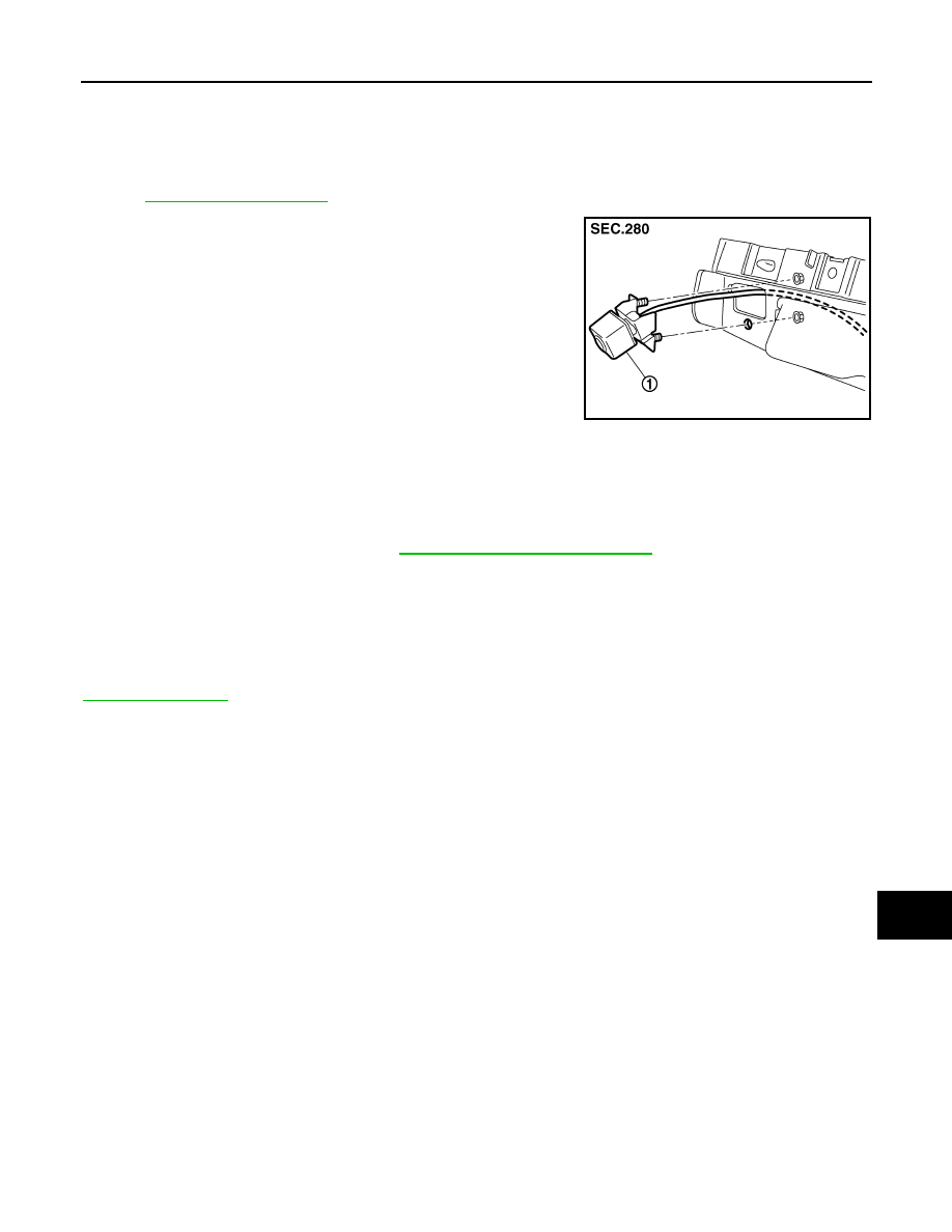
Removal and Installation
INFOID:0000000009163326
REMOVAL
1.
Remove license lamp bracket. Refer to
EXT-21, "Removal and Installation"
2.
Remove the mounting nuts of rear view camera.
3.
Remove rear view camera from license lamp bracket.
INSTALLATION
Install in the reverse order of removal.
NOTE:
Adjust the guide line position if the guide line position is shifted after installing the rear view camera. Refer to
.
Adjustment
INFOID:0000000009163327
Adjust the guide line position if the guide line position is shifted after installing the rear view camera.
JSNIA4792ZZ
1.
Rear view camera