Nissan Pathfinder (2012 year). Manual - part 623


  Index      Manuals     Nissan Pathfinder (2012 year) - Service and Repair Manual


Search            copyright infringement  


Content      ..     621      622      623      624     ..


Nissan Pathfinder (2012 year). Manual - part 623


LOW TIRE PRESSURE WARNING LAMP BLINKS

WT-41

< SYMPTOM DIAGNOSIS >

C

D

F

G

H

I

J

K

L

M

A

B

WT

N

O

P

LOW TIRE PRESSURE WARNING LAMP BLINKS

Low Tire Pressure Warning Lamp Flashes When Ignition Switch Is Turned On

INFOID:0000000007357071

Regarding Wiring Diagram information, refer to 

WT-34, "Wiring Diagram"

.

NOTE:

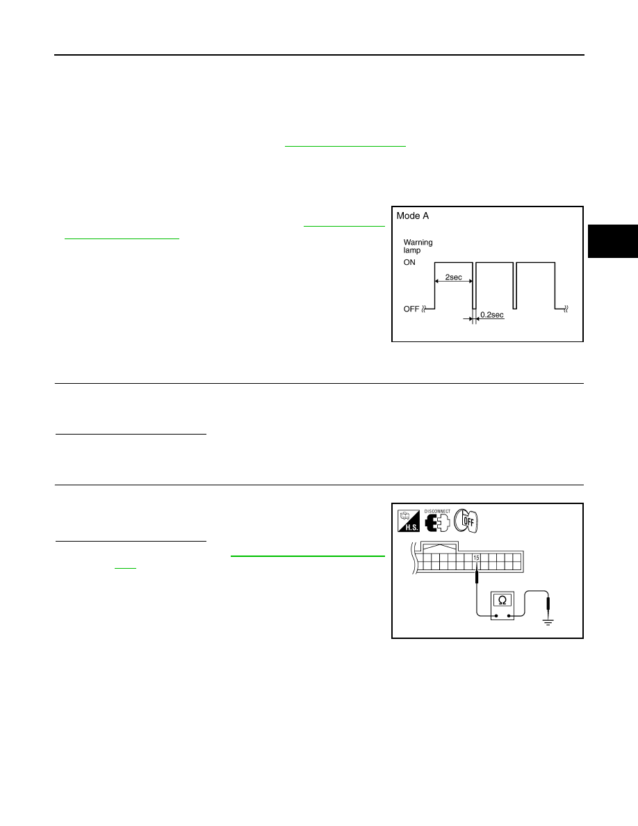
If low tire pressure warning lamp flashes as shown, the system is normal.

Flash Mode A

• This mode shows transmitter status is OFF-mode.

Carry out transmitter wake up operation. Refer to 

WT-5, "Transmit-

ter Wake Up Operation"

.

DIAGNOSTIC PROCEDURE

1.

CHECK BCM CONNECTORS

1. Turn ignition switch OFF.

2. Disconnect BCM harness connectors.

3. Check terminals for damage or loose connections.
Is the inspection result normal?

YES

>> GO TO 2

NO

>> Repair or replace damaged parts.

2.

CHECK TIRE PRESSURE WARNING CHECK CONNECTOR CIRCUIT

Check continuity between BCM harness connector M18 terminal 15 and ground.

Is the inspection result normal?

YES

>> Replace BCM. Refer to 

BCS-53, "Removal and Installa-

tion"

.

NO

>> Repair circuit for short to ground.

SEIA0347E

Continuity should not exist.

ALEIA0014ZZ

August 2012

2012 Pathfinder

WT-42

< SYMPTOM DIAGNOSIS >

HAZARD WARNING LAMPS FLASH

HAZARD WARNING LAMPS FLASH

Hazard Warning Lamps Flash When Ignition Switch Is Turned On

INFOID:0000000007357072

DIAGNOSTIC PROCEDURE

1.

CHECK BCM GROUND CIRCUIT

Check BCM ground circuit.  Refer to 

BCS-30, "Diagnosis Procedure"

.

Is the inspection result normal?

YES

>> Replace BCM. Refer to 

BCS-53, "Removal and Installation"

.

NO

>> Repair BCM ground circuit.

August 2012

2012 Pathfinder

"TIRE PRESSURE" INFORMATION IN DISPLAY UNIT DOES NOT EXIST

WT-43

< SYMPTOM DIAGNOSIS >

C

D

F

G

H

I

J

K

L

M

A

B

WT

N

O

P

"TIRE PRESSURE" INFORMATION IN DISPLAY UNIT DOES NOT EXIST

"TIRE PRESSURE" Information in Display Unit Does Not Exist

INFOID:0000000007357073

NOTE:

The Signal Tech II Tool (J-50190) can be used to perform the following functions. Refer to the Signal Tech II

User Guide for additional information.

• Activate and display TPMS transmitter IDs

• Display tire pressure reported by the TPMS transmitter

• Read TPMS DTCs

• Register TPMS transmitter IDs

DIAGNOSTIC PROCEDURE

1.

SELF-DIAGNOSTIC RESULT CHECK

Using CONSULT, check display contents in self-diagnostic results.
Is CAN COMM CIRCUIT displayed in the self-diagnosis display items?

YES

>>  Malfunction in CAN communication system.

NO

>> GO TO 2.

2.

CHECK DISPLAY UNIT

Perform AV unit self-diagnosis. Refer to  

AV-306, "AV CONTROL UNIT : CONSULT Function"

.

Is the inspection result normal?

OK

>> Replace BCM. Refer to 

BCS-53, "Removal and Installation"

.

NG

>> Repair or replace malfunctioning parts.

August 2012

2012 Pathfinder

WT-44

< SYMPTOM DIAGNOSIS >

ID REGISTRATION CANNOT BE COMPLETED

ID REGISTRATION CANNOT BE COMPLETED

ID Registration Cannot Be Completed

INFOID:0000000007357074

NOTE:

The Signal Tech II Tool (J-50190) can be used to perform the following functions. Refer to the Signal Tech II

User Guide for additional information.

• Activate and display TPMS transmitter IDs

• Display tire pressure reported by the TPMS transmitter

• Read TPMS DTCs

• Register TPMS transmitter IDs

DIAGNOSTIC PROCEDURE

1.

PERFORM ID REGISTRATION OF ALL TRANSMITTERS

Carry out ID registration of all transmitters. Refer to 

WT-6, "ID Registration Procedure"

.

Can ID registration of all transmitters be completed?

YES

>> Inspection End.

NO

>> GO TO 

WT-14, "Diagnosis Procedure"

.

August 2012

2012 Pathfinder

PRECAUTIONS

WT-45

< PRECAUTION >

C

D

F

G

H

I

J

K

L

M

A

B

WT

N

O

P

PRECAUTION

PRECAUTIONS

Precaution for Supplemental Restraint System (SRS) "AIR BAG" and "SEAT BELT 
PRE-TENSIONER"

INFOID:0000000007357075

The Supplemental Restraint System such as “AIR BAG” and “SEAT BELT PRE-TENSIONER”, used along

with a front seat belt, helps to reduce the risk or severity of injury to the driver and front passenger for certain

types of collision. This system includes seat belt switch inputs and dual stage front air bag modules. The SRS

system uses the seat belt switches to determine the front air bag deployment, and may only deploy one front

air bag, depending on the severity of a collision and whether the front occupants are belted or unbelted.

Information necessary to service the system safely is included in the SR and SB section of this Service Man-

ual.

WARNING:

• To avoid rendering the SRS inoperative, which could increase the risk of personal injury or death in

the event of a collision which would result in air bag inflation, all maintenance must be performed by

an authorized NISSAN/INFINITI dealer.

• Improper maintenance, including incorrect removal and installation of the SRS, can lead to personal

injury caused by unintentional activation of the system. For removal of Spiral Cable and Air Bag

Module, see the SR section.

• Do not use electrical test equipment on any circuit related to the SRS unless instructed to in this

Service Manual. SRS wiring harnesses can be identified by yellow and/or orange harnesses or har-

ness connectors.

PRECAUTIONS WHEN USING POWER TOOLS (AIR OR ELECTRIC) AND HAMMERS

WARNING:

• When working near the Airbag Diagnosis Sensor Unit or other Airbag System sensors with the Igni-

tion ON or engine running, DO NOT use air or electric power tools or strike near the sensor(s) with a

hammer. Heavy vibration could activate the sensor(s) and deploy the air bag(s), possibly causing

serious injury.

• When using air or electric power tools or hammers, always switch the Ignition OFF, disconnect the

battery, and wait at least 3 minutes before performing any service.

Precaution Necessary for Steering Wheel Rotation After Battery Disconnect

INFOID:0000000007357076

NOTE:

• This Procedure is applied only to models with Intelligent Key system and NATS (NISSAN ANTI-THEFT SYS-

TEM).

• Remove and install all control units after disconnecting both battery cables with the ignition knob in the

LOCK

 position.

• Always use CONSULT to perform self-diagnosis as a part of each function inspection after finishing work. If

DTC is detected, perform trouble diagnosis according to self-diagnostic results.

For models equipped with the Intelligent Key system and NATS, an electrically controlled steering lock mech-

anism is adopted on the key cylinder.

For this reason, if the battery is disconnected or if the battery is discharged, the steering wheel will lock and

steering wheel rotation will become impossible.

If steering wheel rotation is required when battery power is interrupted, follow the procedure below before

starting the repair operation.

OPERATION PROCEDURE

1. Connect both battery cables.

NOTE:

Supply power using jumper cables if battery is discharged.

2. Use the Intelligent Key or mechanical key to turn the ignition switch to the 

ACC

 position. At this time, the

steering lock will be released.

3. Disconnect both battery cables. The steering lock will remain released and the steering wheel can be

rotated.

4. Perform the necessary repair operation.

August 2012

2012 Pathfinder

WT-46

< PRECAUTION >

PRECAUTIONS

5. When the repair work is completed, return the ignition switch to the 

LOCK

 position before connecting

the battery cables. (At this time, the steering lock mechanism will engage.)

6. Perform a self-diagnosis check of all control units using CONSULT. 

Precaution for Road Wheel

INFOID:0000000007829926

• Genuine NISSAN aluminum wheel is designed for each type of vehicle. Use it on the specified vehicle only.

• Use Genuine NISSAN parts for the wheel nuts.

• Always adjusting the wheel balance prior to using them. For the balance weights, use Genuine NISSAN alu-

minum wheel weights.

• Use caution when handling the aluminum wheels, because they can be easily scratched. When removing

dirt, do not use any abrasives, a wire brush, or other items that may scratch the coating. Use a neutral deter-

gent if a detergent is needed.

• After driving on roads scattered with anti-icing salts, wash off the wheels completely.

• When installing road wheels onto the vehicle, always wipe off any dirt or foreign substances to prevent them

from being trapped between the contact surfaces of wheel.

• Never apply oil to nut and bolt threads.

August 2012

2012 Pathfinder

PREPARATION

WT-47

< PREPARATION >

C

D

F

G

H

I

J

K

L

M

A

B

WT

N

O

P

PREPARATION

PREPARATION

Special Service Tool

INFOID:0000000007357078

The actual shapes of Kent-Moore tools may differ from those of special service tools illustrated here.

Commercial Service Tool

INFOID:0000000007357079

Tool number 
(Kent-Moore No.)
Tool name

Description

KV991B1000
(J-45295)
Transmitter activation tool

• Transmitter wake up operation
• ID registration procedure

WEIA0144E

Tool name

Description

Power tool

Loosening nuts, screws and bolts

PIIB1407E

August 2012

2012 Pathfinder

WT-48

< SYMPTOM DIAGNOSIS >

NOISE, VIBRATION, AND HARSHNESS (NVH) TROUBLESHOOTING

SYMPTOM DIAGNOSIS

NOISE, VIBRATION, AND HARSHNESS (NVH) TROUBLESHOOTING

NVH Troubleshooting Chart

INFOID:0000000007357080

Use chart below to help you find the cause of the symptom. If necessary, repair or replace these parts.

×

: Applicable

Reference page

WT

-49

W

T-5

0, "Adj

us

tm

en

t"

WT

-55

WT

-50

WT

-55

DL

N-35

0,

 "NVH T

rou

bl

es

ho

ot

in

g Cha

rt

"

 (R18

0A),

DLN-38

5,

 "NVH T

ro

ub

les

h

oot

in

g Ch

art"

 (M

20

5)

DL

N-41

8,

 "NVH T

rou

bl

es

ho

ot

in

g Cha

rt"

 (R20

0),

DL

N-45

5, 

"NVH T

ro

ubl

es

ho

ot

ing

 Cha

rt"

 (R

23

0)

FA

X-5,

 "NVH T

ro

ub

les

ho

ot

ing

 Ch

art"

 (F

AX)

F

S

U-6,

 "NVH T

ro

ub

les

ho

ot

ing

 Ch

art"

 (FSU)

RA

X-5,

 "NVH T

ro

ub

les

ho

ot

ing

 Ch

art"

 (R

A

X

)

RSU-5,

 "NVH T

ro

ub

les

ho

ot

ing

 Ch

art"

 (R

S

U

)

Refe

r to

 TI

RES in

 th

is cha

rt.

Refe

r to

 ROAD WHEE

L i

n t

his cha

rt.

B

R

-6

, "

N

V

H

 T

rou

bl

es

ho

oti

ng

 Cha

rt"

ST

-1

1, 

"NVH T

ro

ubl

es

ho

ot

ing

 Cha

rt"

Possible cause and SUSPECTED 
PARTS

O

ut

-of-ro

un

d

Im

ba

la

nc

e

Incorrect t

ire 

pressure

Un

ev

en

 t

ire 

we

ar

Def

orm

ati

on

 or 

da

ma

ge

No

n-u

n

iform

ity

In

co

rrec

t t

ire 

si

ze

FRONT F

INAL 

DRI

VE

REAR FINAL 

DR

IVE

FRONT A

X

LE 

AND FRONT SUSPE

NSION

REAR A

XLE 

AND REAR SUSPE

NSION

TI

RE

S

ROAD WHEE

L

BRAKE

STE

E

RING

Symptom

TIRES

Noise

×

×

×

×

×

×

×

×

×

×

×

×

×

Shake

×

×

×

×

×

×

×

×

×

×

×

Vibration

×

×

×

×

×

×

Shimmy

×

×

×

×

×

×

×

×

×

×

×

×

Shudder

×

×

×

×

×

×

×

×

×

×

×

Poor quality ride 
or handling

×

×

×

×

×

×

×

×

×

ROAD 
WHEEL

Noise

×

×

×

×

×

×

×

×

×

×

Shake

×

×

×

×

×

×

×

×

Shimmy, shud-
der

×

×

×

×

×

×

×

×

Poor quality ride 
or handling

×

×

×

×

×

×

August 2012

2012 Pathfinder


Content      ..     621      622      623      624     ..