Nissan Pathfinder (2012 year). Manual - part 591


  Index      Manuals     Nissan Pathfinder (2012 year) - Service and Repair Manual


Search            copyright infringement  


Content      ..     589      590      591      592     ..


Nissan Pathfinder (2012 year). Manual - part 591


PREPARATION

TM-155

< PREPARATION >

C

E

F

G

H

I

J

K

L

M

A

B

TM

N

O

P

PREPARATION

PREPARATION

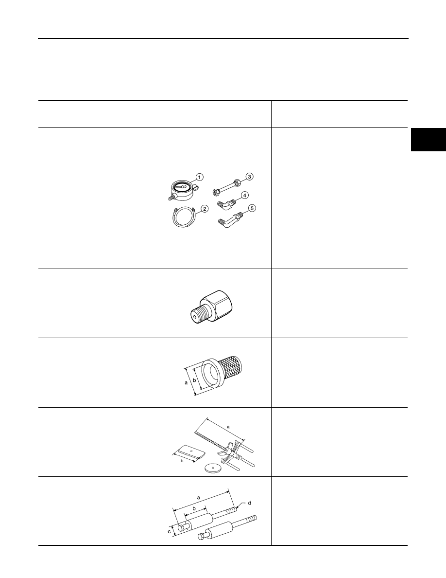
Special Service Tool

INFOID:0000000007357289

The actual shapes of Kent-Moore tools may differ from those of special service tools illustrated here.

Tool number
(Kent-Moore No.)
 Tool name

Description

ST2505S001
(J-34301-C)
Oil pressure gauge set
1 ST25051001
( — )
Oil pressure gauge
2 ST25052000
( — )
Hose
3 ST25053000
( — )
Joint pipe
4 ST25054000
( — )
Adapter
5 ST25055000
( — )
Adapter

Measuring line pressure

KV31103600
(J-45674)
Joint pipe adapter
(With ST25054000)

Measuring line pressure

ST33400001
(J-26082)
Drift

• Installing rear oil seal (2WD models)
• Installing oil pump housing oil seal

a: 60 mm (2.36 in) dia.
b: 47 mm (1.85 in) dia.

KV31102400
(J-34285 and J-34285-87)
Clutch spring compressor

Installing reverse brake return spring retainer

a: 320 mm (12.60 in)
b: 174 mm (6.85 in)

ST25850000
(J-25721-A)
Sliding hammer

Remove oil pump assembly

a: 179 mm (7.05 in)
b: 70 mm (2.76 in)
c: 40 mm (1.57 in)
d: M12X1.75P

LCIA0399E

ZZA1227D

NT086

NT423

NT422

August 2012

2012 Pathfinder

TM-156

< PREPARATION >

PREPARATION

Commercial Service Tool

INFOID:0000000007357290

(J-47002)
Transmission jack adapter kit
1.

(J-47002-1)
Center bracket
2.

(J-47002-3)
Adapter plate
3.

(J-47002-4)
Adapter block

Assist in removal of transmission and transfer 
case as one assembly using only one trans-
mission jack.

(J-46534)
Trim tool set

Removing trim components

Tool number
(Kent-Moore No.)
 Tool name

Description

WCIA0499E

AWJIA0483ZZ

Tool name

Description

Power tool

Loosening nuts, screws and bolts

Drift

Installing manual shaft seals

a: 22 mm (0.87 in) dia.

Drift

Installing rear oil seal (4WD models)

a: 64 mm (2.52 in) dia.

Pin punch

• Removing retaining pin
• Installing retaining pin

a: 4 mm (0.16 in) dia.

PIIB1407E

NT083

SCIA5338E

NT410

August 2012

2012 Pathfinder

A/T FLUID

TM-157

< PERIODIC MAINTENANCE >

C

E

F

G

H

I

J

K

L

M

A

B

TM

N

O

P

PERIODIC MAINTENANCE

A/T FLUID

Checking the A/T Fluid (ATF)

INFOID:0000000007357291

CAUTION:

If using the vehicle for towing, the A/T fluid must be replaced as specified. Refer to 

MA-11, "FOR USA

AND CANADA : Introduction to Periodic Maintenance"

 (United States and Canada) and 

MA-15, "FOR

MEXICO : Periodic Maintenance Schedule"

 (Mexico).

1. Before driving, the A/T fluid level can be checked at A/T fluid

temperatures of 30

°

 to 50

°

 C (86

°

 to 122

°

 F) using the “COLD”

range on the A/T fluid level gauge as follows:

a. Park the vehicle on a level surface and set the parking brake.
b. Start the engine and move the selector lever through each gear

position. Shift the selector lever into the “P” position.

c. Check the A/T fluid level with the engine idling.
d. Remove the A/T fluid level gauge and wipe it clean with a lint-

free paper.

CAUTION:

When wiping the A/T fluid from the A/T fluid level gauge,

always use a lint-free paper, not a cloth.

e. Re-insert the A/T fluid level gauge into the A/T fluid charging

pipe until the cap contacts the top of the A/T fluid charging pipe

as shown.

CAUTION:

To check A/T fluid level, insert the A/T fluid level gauge until

the cap contacts the top of the A/T fluid charging pipe, with

the gauge reversed from the normal inserted position.

f.

Remove the A/T fluid level gauge and note the A/T fluid level. If

the A/T fluid level is at low side of range, add A/T fluid to the

transmission through the A/T fluid charging pipe.

CAUTION:

Do not overfill the transmission with A/T fluid.

g. Install the A/T fluid level gauge and the A/T fluid level gauge bolt.

2. Warm up the engine and transmission.
3. Check for any A/T fluid leaks.
4. Drive the vehicle to increase the A/T fluid temperature to 80

°

 C (176

°

 F).

LLIA0071E

A/T fluid level gauge bolt

: Refer to 

TM-195, "2WD : Exploded View"


(2WD) or 

TM-198, "4WD : Exploded View"


(4WD).

SCIA2899E

August 2012

2012 Pathfinder

TM-158

< PERIODIC MAINTENANCE >

A/T FLUID

5. Allow the A/T fluid temperature to fall to approximately 65

°

C (149

°

F). Use the CONSULT to monitor the A/

T fluid temperature as follows:

NOTE:

The A/T fluid level will be significantly affected by the A/T fluid temperature as shown. Therefore monitor

the A/T fluid temperature data using the CONSULT.

a. Connect CONSULT to data link connector.
b. Select “MAIN SIGNALS” in “DATA MONITOR” mode for “A/T” with CONSULT.
c.

Read out the value of “ATF TEMP 1”.

6. Re-check the A/T fluid level at A/T fluid temperatures of approxi-

mately 65

°

C (149

°

F) using the “HOT” range on the A/T fluid

level gauge as shown. The HOT range is between 50

°

 - 80

°

 C

(122

°

 - 176

°

 F).

CAUTION:

• When wiping the A/T fluid from the A/T fluid level gauge,

always use lint-free paper, not a cloth.

• To check the A/T fluid level, insert the A/T fluid level

gauge until the cap contacts the top of the A/T fluid charg-

ing pipe, with the gauge reversed from the normal

inserted position as shown.

7. Check the A/T fluid condition.

• If the A/T fluid is very dark or has some burned smell, there

may be an internal problem with the transmission. Refer to

TM-116

. Flush the transmission cooling system after repairing

the transmission.

• If the A/T fluid contains frictional material (clutches, bands,

etc.), replace the radiator and flush the transmission cooler

lines using cleaning solvent and compressed air after repairing

the transmission.

8. Install the A/T fluid level gauge in the A/T fluid charging pipe.
9. Tighten the A/T fluid level gauge bolt to specification.

SLIA0016E

LLIA0071E

A/T fluid level gauge bolt

: Refer to 

TM-195, "2WD : Exploded View"


(2WD) or 

TM-198, "4WD : Exploded View"


(4WD).

SCIA2899E

August 2012

2012 Pathfinder

A/T FLUID

TM-159

< PERIODIC MAINTENANCE >

C

E

F

G

H

I

J

K

L

M

A

B

TM

N

O

P

Changing the A/T Fluid (ATF)

INFOID:0000000007357292

CAUTION:

If using the vehicle for towing, the A/T fluid must be replaced as specified. Refer to 

MA-11, "FOR USA

AND CANADA : Introduction to Periodic Maintenance"

 (United States and Canada) and 

MA-15, "FOR

MEXICO : Periodic Maintenance Schedule"

 (Mexico).

1. Drive the vehicle to warm up the A/T fluid to approximately 80

°

 C (176

°

 F).

2. Stop the engine.
3. Remove the A/T fluid level gauge.
4. Drain the A/T fluid from the drain plug hole, then install the drain

plug with a new gasket. Refill the transmission with new A/T

fluid. Always refill with the same volume as the drained A/T fluid.

Use the A/T fluid level gauge to check the A/T fluid level as

shown. Add A/T fluid as necessary.

• To flush out the old A/T fluid from the transmission oil coolers, pour new A/T fluid into the A/T fluid charg-

ing pipe with the engine idling and at the same time drain the old A/T fluid from the auxiliary transmis-

sion oil cooler hose return line.

• When the color of the A/T fluid coming out of the auxiliary transmission oil cooler hose return line is

about the same as the color of the new A/T fluid, flushing out the old A/T fluid is complete. The amount

of new A/T fluid used for flushing should be 30% to 50% increase of the specified capacity.

CAUTION:

• If Genuine NISSAN Matic S ATF is not available, Genuine NISSAN Matic J ATF may also be used.

Using automatic transmission fluid other than Genuine NISSAN Matic S or Matic J will cause

deterioration in driveability. and may damage automatic transmission, which is not covered by

the NISSAN new vehicle limited warranty.

• When filling the transmission with A/T fluid, do not spill the A/T fluid on any heat generating

parts such as the exhaust manifold.

• Do not reuse the drain plug gasket.

5. Install the A/T fluid level gauge and tighten the A/T fluid level gauge bolt to specification.

6. Drive the vehicle to warm up the A/T fluid to approximately 80

°

 C (176

°

 F).

7. Check the fluid level and condition. If the A/T fluid is still dirty,

repeat steps 2 through 6.

Drain plug

Refer to 

TM-174, "Removal and 

Installation"

.

LLIA0071E

A/T fluid grade and capacity

: Refer to 

MA-11, "FOR USA AND CANADA : Introduction to Pe-

riodic Maintenance"

 (United States and Canada) and 

MA-15, 

"FOR MEXICO : Periodic Maintenance Schedule"

 (Mexico).

A/T fluid level gauge bolt

: Refer to 

TM-195, "2WD : Exploded View"


(2WD) or 

TM-198, "4WD : Exploded View"


(4WD).

LLIA0071E

August 2012

2012 Pathfinder

TM-160

< PERIODIC MAINTENANCE >

A/T FLUID

8. Install the A/T fluid level gauge in the A/T fluid charging pipe and install the A/T fluid level gauge bolt.
9. Tighten the A/T fluid level gauge bolt to specification.

A/T Fluid Cooler Cleaning

INFOID:0000000007357293

Whenever an A/T is repaired, overhauled, or replaced, the A/T fluid cooler mounted in the radiator must be

inspected and cleaned.

Metal debris and friction material, if present, can become trapped in the A/T fluid cooler. This debris can con-

taminate the newly serviced A/T or, in severe cases, can block or restrict the flow of A/T fluid. In either case,

malfunction of the newly serviced A/T may result.

Debris, if present, may build up as A/T fluid enters the cooler inlet. It will be necessary to back flush the cooler

through the cooler outlet in order to flush out any built up debris.

A/T FLUID COOLER CLEANING PROCEDURE

1. Position a drain pan under the A/T inlet and outlet fluid cooler tube to cooler hose connection.
2. Put a different color matching mark on each cooler tube to cooler hose connection to aid in assembly.

CAUTION:

Use paint to make the matching mark. Do not damage the tubes or hose.

3. Disconnect the fluid cooler inlet and outlet rubber hoses from the

steel cooler tubes.

NOTE:

Replace the cooler hoses if rubber material from the hose

remains on the tube fitting.

4. Drain any A/T fluid from the cooler hose.

5. Insert the extension adapter hose of a can of Transmission

Cooler Cleaner (Nissan P/N 999MP-AM006) into the cooler out-

let hose.

CAUTION:

• Wear safety glasses and rubber gloves when spraying the

Transmission Cooler Cleaner.

• Spray cooler cleaner only with adequate ventilation.

• Avoid contact with eyes and skin.

• Do not breath vapors or spray mist.

6. Hold the hose and can as high as possible and spray Transmis-

sion Cooler Cleaner in a continuous stream into the cooler outlet

hose until fluid flows out of the cooler inlet hose for 5 seconds.

7. Insert the tip of an air gun into the end of the cooler outlet hose.
8. Wrap a shop rag around the tip of the air gun and the cooler out-

let hose.

A/T fluid level gauge bolt

: Refer to 

TM-195, "2WD : Exploded View"


(2WD) or 

TM-198, "4WD : Exploded View"


(4WD).

SCIA3830E

SCIA3831E

SCIA3832E

August 2012

2012 Pathfinder

A/T FLUID

TM-161

< PERIODIC MAINTENANCE >

C

E

F

G

H

I

J

K

L

M

A

B

TM

N

O

P

9. Blow compressed air regulated to 5 - 9 kg/cm

2

 (70 - 130 psi) through the cooler outlet hose for 10 seconds

to force out any remaining fluid.

10. Repeat steps 5 through 9 three additional times.
11. Position an oil pan under the banjo bolts that connect the fluid cooler tubes to the A/T.
12. Remove the banjo bolts.
13. Flush each steel line from the cooler side back toward the A/T by spraying Transmission Cooler Cleaner

in a continuous stream for 5 seconds.

14. Blow compressed air regulated to 5 - 9 kg/cm

2

 (70 - 130 psi) through each steel line from the cooler side

back toward the A/T for 10 seconds to force out any remaining fluid.

15. Ensure all debris is removed from the steel cooler lines.
16. Ensure all debris is removed from the banjo bolts and fittings.
17. Perform "A/T FLUID COOLER DIAGNOSIS PROCEDURE".

A/T FLUID COOLER DIAGNOSIS PROCEDURE

NOTE:

Insufficient cleaning of the cooler inlet hose exterior may lead to inaccurate debris identification.
1. Position a drain pan under the A/T inlet and outlet fluid cooler tube to cooler hose connection.
2. Clean the exterior and tip of the cooler inlet hose.
3. Put a different color matching mark on each cooler tube to cooler hose connection to aid in assembly.

CAUTION:

Use paint to make the matching mark. Do not damage the tubes or hose.

4. Disconnect the fluid cooler inlet and outlet rubber hoses from the

steel cooler tubes.

NOTE:

Replace the cooler hoses if rubber material from the hose

remains on the tube fitting.

5. Insert the extension adapter hose of a can of Transmission

Cooler Cleaner (Nissan P/N 999MP-AM006) into the cooler out-

let hose.

CAUTION:

• Wear safety glasses and rubber gloves when spraying the

Transmission Cooler Cleaner.

• Spray cooler cleaner only with adequate ventilation.

• Avoid contact with eyes and skin.

• Do not breath vapors or spray mist.

6. Hold the hose and can as high as possible and spray Transmis-

sion Cooler Cleaner in a continuous stream into the cooler outlet

hose until fluid flows out of the cooler inlet hose for 5 seconds.

7. Tie a common white, basket-type coffee filter to the end of the

cooler inlet hose.

SCIA3830E

SCIA3831E

SCIA3833E

August 2012

2012 Pathfinder

TM-162

< PERIODIC MAINTENANCE >

A/T FLUID

8. Insert the tip of an air gun into the end of the cooler outlet hose.
9. Wrap a shop rag around the air gun tip and end of cooler outlet

hose.

10. Blow compressed air regulated to 5 - 9 kg/cm

2

   (70 - 130 psi)

through the cooler outlet hose to force any remaining A/T fluid

into the coffee filter.

11. Remove the coffee filter from the end of the cooler inlet hose.
12. Perform A/T fluid cooler inspection. Refer to 

TM-157, "Checking

the A/T Fluid (ATF)"

.

A/T FLUID COOLER INSPECTION PROCEDURE

1. Inspect the coffee filter for debris.
a. If small metal debris less than 1mm (0.040 in) in size or metal

powder is found in the coffee filter, this is normal. If normal

debris is found, the A/T fluid cooler/radiator can be re-used and

the procedure is ended.

b. If one or more pieces of debris are found that are over 1mm

(0.040 in) in size and/or peeled clutch facing material is found in

the coffee filter, the fluid cooler is not serviceable. The A/T fluid

cooler/radiator must be replaced and the inspection procedure is

ended. Refer to 

CO-17, "Removal and Installation"

  for

(VQ40DE) 

CO-46, "Removal and Installation"

 for (VK56DE).

A/T FLUID COOLER FINAL INSPECTION

After performing all procedures, ensure that all remaining oil is cleaned from all components.

SCIA3834E

SCIA2967E

SCIA5659E

August 2012

2012 Pathfinder


Content      ..     589      590      591      592     ..