Nissan Pathfinder (2012 year). Manual - part 566
ST-20
< REMOVAL AND INSTALLATION >
STEERING WHEEL
STEERING WHEEL
Removal and Installation
INFOID:0000000007356583
REMOVAL
1. Set the front wheels in the straight-ahead position.
2. Remove the driver air bag module. Refer to
SR-5, "Removal and Installation"
3. Disconnect the steering wheel switches and heated steering wheel connector.
4. Remove the steering wheel center nut.
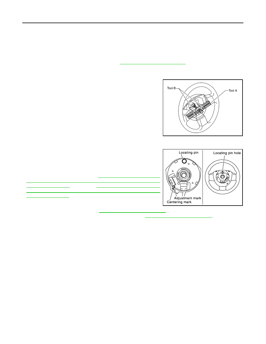
5. Remove the steering wheel, using Tools.
6. Inspect the steering wheel near the puller holes for damage. If
damage is found, replace the steering wheel.
• Remove the steering wheel rear cover and steering wheel
switches, if required.
CAUTION:
Place a piece of tape across the spiral cable so it will not be
rotated out of position.
INSTALLATION
Installation is in the reverse order of removal.
• Align spiral cable correctly when installing steering wheel. Make
sure that the spiral cable is in the neutral position. The neutral
position is detected by turning left 2.5 revolutions from the right
end position and ending with the locating pin at the top.
• If equipped with VDC, refer to
STEERING ANGLE SENSOR NEUTRAL POSITION : Special
(TYPE 1),
STEERING ANGLE SENSOR NEUTRAL POSITION : Special
(TYPE 2) for steering angle sensor adjust-
ment.
• After the work is completed, perform self-diagnosis to make sure
no malfunction is detected. Refer to
.
• Tighten steering wheel center nut to specification. Refer to
ST-17, "Removal and Installation"
.
CAUTION:
• The spiral cable may snap due to steering operation if the cable is not installed in the correct posi-
tion.
• With the steering linkage disconnected, the cable may snap by turning the steering wheel beyond
the limited number of turns. The spiral cable can be turned counterclockwise about 2.5 turns from
the neutral position.
Tool number
A: KV481J0010 (J-1859A)
B: KV481J0020 (J-42578)
WHIA0124E
PHIA0275E
August 2012
2012 Pathfinder
2012 Pathfinder