Nissan Pathfinder (2012 year). Manual - part 509
DIAGNOSIS AND REPAIR WORKFLOW
RF-3
< BASIC INSPECTION >
C
D
E
F
G
H
I
J
L
M
A
B
RF
N
O
P
BASIC INSPECTION
DIAGNOSIS AND REPAIR WORKFLOW
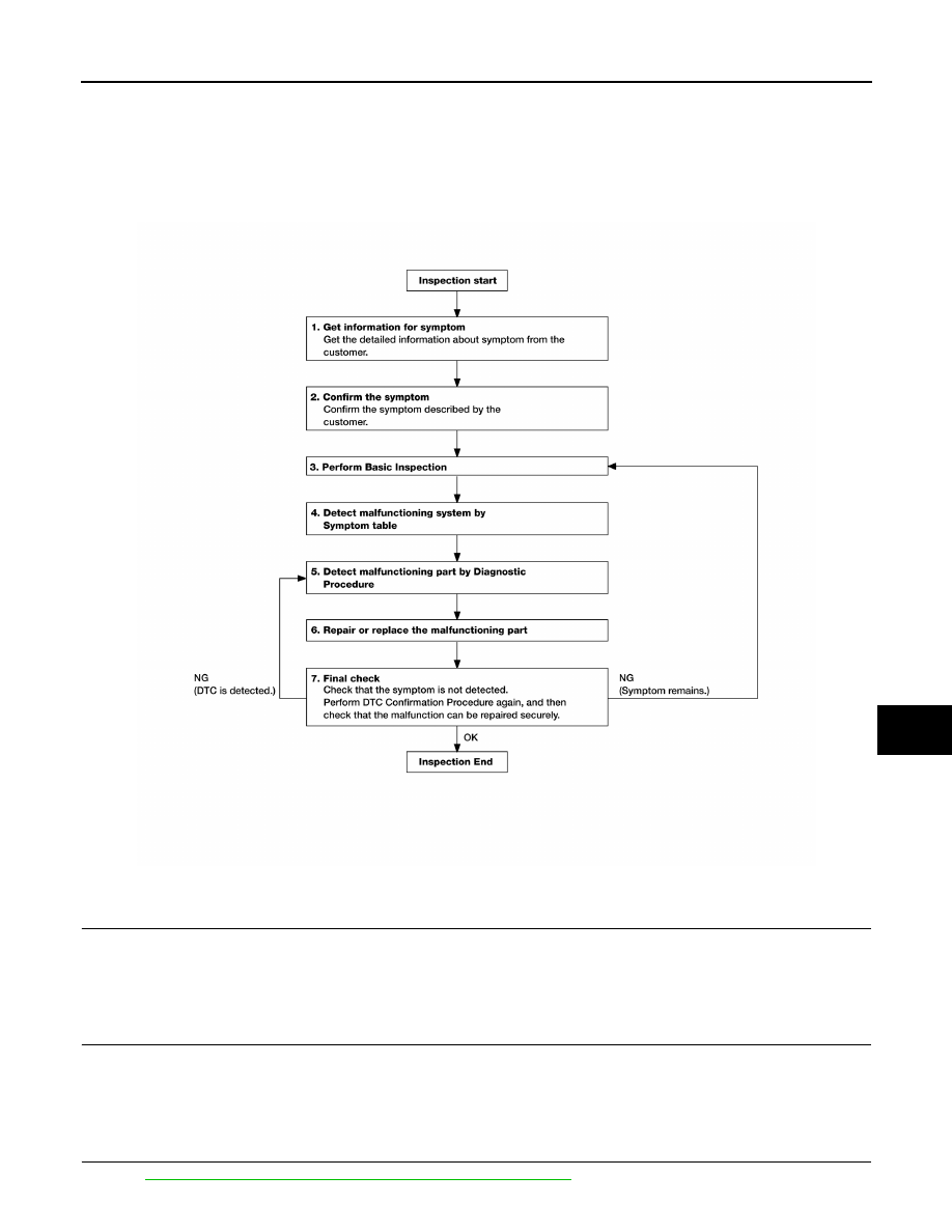
Work Flow
INFOID:0000000007355935
OVERALL SEQUENCE
DETAILED FLOW
1.
GET INFORMATION FOR SYMPTOM
Get the detailed information from the customer about the symptom (the condition and the environment when
the incident/malfunction occurred).
>> GO TO 2
2.
CONFIRM THE SYMPTOM
Confirm the symptom described by the customer.
Verify relation between the symptom and the condition when the symptom is detected.
>> GO TO 3
3.
PERFORM BASIC INSPECTION
Perform
RF-5, "BASIC INSPECTION : Special Repair Requirement"
.
ABKIA2887GB
August 2012
2012 Pathfinder