Nissan Pathfinder (2012 year). Manual - part 501
PWC-38
< DTC/CIRCUIT DIAGNOSIS >
DOOR KEY CYLINDER SWITCH
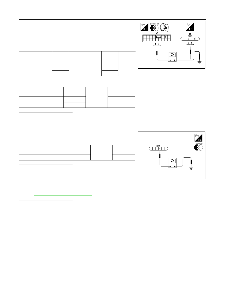
1. Turn ignition switch OFF.
2. Disconnect main power window and door lock/unlock switch and
front door lock assembly LH (key cylinder switch).
3. Check continuity between main power window and door lock/
unlock switch connector (A) and front door lock assembly LH
(key cylinder switch) connector (B).
4. Check continuity between main power window and door lock/unlock switch connector (A) and ground.
Is the inspection result normal?
YES
>> GO TO 3
NO
>> Repair or replace harness.
3.
CHECK DOOR KEY CYLINDER SWITCH GROUND CIRCUIT
Check continuity between front door lock assembly LH (key cylinder
switch) connector and ground.
Is the inspection result normal?
YES
>> GO TO 4
NO
>> Repair or replace harness.
4.
CHECK DOOR KEY CYLINDER SWITCH
Check door key cylinder switch.
PWC-38, "Component Inspection"
Is the inspection result normal?
YES
>> Check intermittent incident. Refer to
GI-37, "Intermittent Incident"
.
NO
>> Replace front door lock assembly LH (door key cylinder switch).
Component Inspection
INFOID:0000000007355895
COMPONENT INSPECTION
1.
CHECK DOOR KEY CYLINDER SWITCH
Main power window
and door lock/unlock
switch connector
Terminal
Front door lock as-
sembly LH (key cylin-
der switch) connector
Terminal
Continuity
D7 (A)
4
D14 (B)
5
Yes
6
3
Main power window and door
lock/unlock switch connector
Terminal
Ground
Continuity
D7 (A)
4
No
6
ALKIA1212ZZ
Front door lock assembly LH (key
cylinder switch) connector
Terminal
Ground
Continuity
D14
4
Yes
LIIA2806E
August 2012
2012 Pathfinder