Nissan Pathfinder (2012 year). Manual - part 484


  Index      Manuals     Nissan Pathfinder (2012 year) - Service and Repair Manual


Search            copyright infringement  


Content      ..     482      483      484      485     ..


Nissan Pathfinder (2012 year). Manual - part 484


PCS-8

< SYSTEM DESCRIPTION >

[IPDM E/R]

POWER CONSUMPTION CONTROL SYSTEM

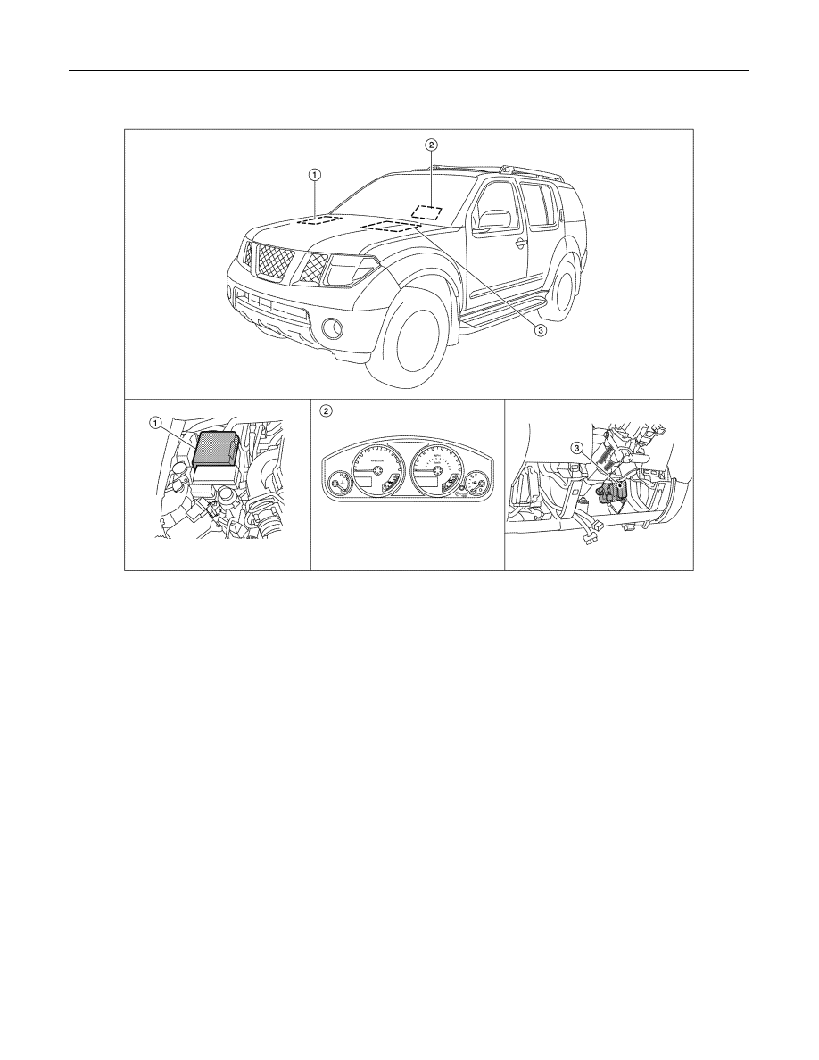
Component Parts Location

INFOID:0000000007355022

1.

IPDM E/R E118, E119, E120, E121, 
E122, E123, E124

2.

Combination meter M24

3.

BCM (view with lower instrument 
panel LH removed) M18, M19, M20

ALMIA0311ZZ

August 2012

2012 Pathfinder

PCS

DIAGNOSIS SYSTEM (IPDM E/R)

PCS-9

< SYSTEM DESCRIPTION >

[IPDM E/R]

C

D

E

F

G

H

I

J

K

L

B

A

O

P

N

DIAGNOSIS SYSTEM (IPDM E/R)

Diagnosis Description

INFOID:0000000007355023

AUTO ACTIVE TEST

Description

In auto active test mode, the IPDM E/R sends a drive signal to the following systems to check their operation.

• Oil pressure low warning indicator

• Oil pressure gauge

• Rear window defogger

• Front wipers

• Tail, license and parking lamps

• Front fog lamps (if equipped)

• Headlamps (Hi, Lo)

• A/C compressor (magnetic clutch)

• Cooling fan

Operation Procedure

1. Close the hood and front door RH, and lift the wiper arms from the windshield (to prevent windshield dam-

age due to wiper operation).

NOTE:

When auto active test is performed with hood opened, sprinkle water on windshield before hand.

2. Turn ignition switch OFF.
3. Turn the ignition switch ON and, within 20 seconds, press the front door switch LH 10 times. Then turn the

ignition switch OFF.

4. Turn the ignition switch ON within 10 seconds. After that the horn sounds once and the auto active test

starts.

5. After a series of the following operations is repeated 3 times, auto active test is completed.

NOTE:

When auto active test mode has to be cancelled halfway through test, turn ignition switch OFF.

CAUTION:

• If auto active test mode cannot be actuated, check door switch system. Refer to 

DLK-56, "Descrip-

tion"

 (with Intelligent Key system), 

DLK-229, "Description"

 (without Intelligent Key system).

• Do not start the engine.

Inspection in Auto Active Test Mode

When auto active test mode is actuated, the following 7 steps are repeated 3 times.

Operation 
sequence

Inspection Location

Operation

1

Rear window defogger

10 seconds 

2

Front wipers

LO for 5 seconds 

 HI for 5 seconds

WKIA4991E

August 2012

2012 Pathfinder

PCS-10

< SYSTEM DESCRIPTION >

[IPDM E/R]

DIAGNOSIS SYSTEM (IPDM E/R)

Concept of auto active test

• IPDM E/R starts the auto active test with the door switch signals transmitted by BCM via CAN communica-

tion. Therefore, the CAN communication line between IPDM E/R and BCM is considered normal if the auto

active test starts successfully.

• The auto active test facilitates troubleshooting if any systems controlled by IPDM E/R cannot be operated.

Diagnosis chart in auto active test mode

3

Tail, license, front fog and parking lamps

10 seconds

4

Headlamps

LO for 10 seconds 

 HI on-off for 5 seconds

5

A/C compressor (magnetic clutch)

ON 

 OFF 5 times

6

Cooling fan

10 seconds

Operation 
sequence

Inspection Location

Operation

AWMIA1124GB

Symptom

Inspection contents

Possible cause

Oil pressure low warning indicator does not operate

Perform auto active test.
Does the oil pressure low 
warning indicator operate?

YES

• IPDM E/R signal input cir-

cuit

• ECM signal input circuit
• CAN communication signal 

between ECM and combi-
nation meter

NO

• CAN communication signal 

between IPDM E/R, BCM 
and combination meter

Oil pressure gauge does not operate

Perform auto active test.
Does the oil pressure gauge 
operate?

YES

IPDM E/R signal input circuit

NO

• CAN communication signal 

between IPDM E/R, BCM 
and combination meter

Rear window defogger does not operate

Perform auto active test.
Does the rear window defog-
ger operate?

YES

BCM signal input circuit

NO

• Harness or connector be-

tween A/C and AV switch 
assembly and AV control 
unit

• CAN communication signal 

between BCM and IPDM E/
R

August 2012

2012 Pathfinder

PCS

DIAGNOSIS SYSTEM (IPDM E/R)

PCS-11

< SYSTEM DESCRIPTION >

[IPDM E/R]

C

D

E

F

G

H

I

J

K

L

B

A

O

P

N

CONSULT Function (IPDM E/R)

INFOID:0000000007355024

APPLICATION ITEM

CONSULT performs the following functions via CAN communication with IPDM E/R.

SELF DIAGNOSTIC RESULT

Refer to 

PCS-21, "DTC Index"

.

DATA MONITOR

Any of the following components do not operate

• Front wipers
• Tail  lamps
• License plate lamps
• Parking  lamps
• Front fog lamps (if equipped)
• Headlamps (Hi, Lo)

Perform auto active test.
Does the applicable system 
operate?

YES

BCM signal input system

NO

• Lamp or front wiper motor 

malfunction

• Lamp or front wiper motor 

ground circuit

• Harness or connector be-

tween IPDM E/R and appli-
cable system

• IPDM E/R (integrated relay 

malfunction)

A/C compressor does not operate

Perform auto active test.
Does the A/C compressor op-
erate?

YES

• BCM signal input circuit
• CAN communication signal 

between BCM and ECM

• CAN communication signal 

between ECM and IPDM E/
R

NO

• Magnetic clutch malfunction
• Harness or connector be-

tween IPDM E/R and mag-
netic clutch

• IPDM E/R (integrated relay 

malfunction)

Cooling fan does not operate

Perform auto active test.
Does the cooling fan operate?

YES

• ECM signal input circuit
• CAN communication signal 

between ECM and IPDM E/
R

NO

• Cooling fan motor malfunc-

tion

• Harness or connector be-

tween IPDM E/R and cool-
ing fan

• IPDM E/R (integrated relay 

malfunction)

Symptom

Inspection contents

Possible cause

Direct Diagnostic Mode

Description

Self Diagnostic Result

The IPDM E/R self diagnostic results are displayed.

Data Monitor

The IPDM E/R input/output data is displayed in real time.

Active Test

The IPDM E/R activates outputs to test components.

CAN Diag Support Mntr

The result of transmit/receive diagnosis of CAN communication is diplayed.

Monitor Item [Unit]

Main

Signals

Description

MOTOR FAN REQ [1/2/3/4]

×

Indicates cooling fan speed signal received from ECM on CAN communication 
line

AC COMP REQ [On/Off]

×

Indicates A/C compressor request signal received from ECM on CAN commu-
nication line

August 2012

2012 Pathfinder

PCS-12

< SYSTEM DESCRIPTION >

[IPDM E/R]

DIAGNOSIS SYSTEM (IPDM E/R)

ACTIVE TEST

TAIL&CLR REQ [On/Off]

×

Indicates position light request signal received from BCM on CAN communica-
tion line

HL LO REQ [On/Off]

×

Indicates low beam request signal received from BCM on CAN communication 
line

HL HI REQ [On/Off]

×

Indicates high beam request signal received from BCM on CAN communication 
line

FR FOG REQ [On/Off]

×

Indicates front fog light request signal received from BCM on CAN communica-
tion line

FR WIP REQ [Stop/1LOW/Low/Hi]

×

Indicates front wiper request signal received from BCM on CAN communication 
line

WIP AUTO STOP [STOP P/ACT P]

×

Indicates condition of front wiper auto stop signal

WIP PROT [Off/BLOCK]

×

Indicates condition of front wiper fail-safe operation

ST RLY REQ [On/Off]

Indicates starter request signal received from ECM on CAN communication line

IGN RLY [On/Off]

×

Indicates condition of ignition relay

RR DEF REQ [On/Off]

×

Indicates rear defogger request signal received from BCM on CAN communica-
tion line

OIL P SW [Open/Close]

Indicates condition of oil pressure switch

DTRL REQ [Off]

Indicates daytime light request signal received from BCM on CAN communica-
tion line

THFT HRN REQ [On/Off]

Indicates theft warning horn request signal received from BCM on CAN commu-
nication line

HORN CHIRP [On/Off]

Indicates horn reminder signal received from BCM on CAN communication line

Monitor Item [Unit]

Main

Signals

Description

Test item

Description

REAR DEFOGGER

This test is able to check rear defogger operation [On/Off].

FRONT WIPER

This test is able to check wiper motor operation [Hi/Lo/Off].

MOTOR FAN

This test is able to check cooling fan operation [4/3/2/1].

EXTERNAL LAMPS

This test is able to check external lamp operation [Fog/Hi/Lo/TAIL/Off].

HORN

This test is able to check horn operation [On].

August 2012

2012 Pathfinder

PCS

U1000 CAN COMM CIRCUIT

PCS-13

< DTC/CIRCUIT DIAGNOSIS >

[IPDM E/R]

C

D

E

F

G

H

I

J

K

L

B

A

O

P

N

DTC/CIRCUIT DIAGNOSIS

U1000 CAN COMM CIRCUIT

Description

INFOID:0000000007355025

Refer to 

LAN-4, "System Description"

.

DTC Logic

INFOID:0000000007355026

DTC DETECTION LOGIC

DTC CONFIRMATION PROCEDURE

Diagnosis Procedure

INFOID:0000000007355027

1.

 PERFORM SELF DIAGNOSTIC

1. Turn ignition switch ON and wait for 2 seconds or more.

2. Check “SELF-DIAG RESULTS” of IPDM E/R.
Is “CAN COMM CIRCUIT” displayed?

YES

>> Refer to 

LAN-5, "CAN Communication Control Circuit"

.

NO

>> Refer to 

GI-37, "Intermittent Incident"

.

DTC

CONSULT display de-

scription

DTC Detection Condition

Possible cause

U1000

CAN COMM CIRCUIT

When IPDM E/R cannot communicate CAN 
communication signal continuously for 2 
seconds or more

In CAN communication system, any item (or items) 
of the following listed below is malfunctioning.
• Receiving (TCM)
• Receiving (ECM)
• Receiving (BCM)
• Receiving (Combination meter)

August 2012

2012 Pathfinder

PCS-14

< DTC/CIRCUIT DIAGNOSIS >

[IPDM E/R]

POWER SUPPLY AND GROUND CIRCUIT

POWER SUPPLY AND GROUND CIRCUIT

Diagnosis Procedure

INFOID:0000000007355028

Regarding Wiring Diagram information, refer to 

PCS-22, "Wiring Diagram"

.

1.

 CHECK FUSES AND FUSIBLE LINK

Check that the following IPDM E/R fuses or fusible link are not blown.

Is the fuse blown?

YES

>> Replace the blown fuse or fusible link after repairing the affected circuit.

NO

>> GO TO 2

2.

 CHECK BATTERY POWER SUPPLY CIRCUIT

1. Turn ignition switch OFF.

2. Disconnect IPDM E/R.

3. Check voltage between IPDM E/R harness connectors and

ground.

Is the measurement value normal?

YES

>> GO TO 3

NO

>> Repair or replace harness.

3.

 CHECK GROUND CIRCUIT

1. Turn ignition switch OFF.

2. Check continuity between IPDM E/R harness connectors and

ground.

Does continuity exist?

YES

>> Inspection End.

NO

>> Repair or replace harness.

Terminal No.

Signal name

Fuses and fusible link No.

1

Battery

A, D

2

Battery

C

Terminals

Ignition switch position

(+)

(

)

OFF

ON

START

Connector

Terminal

E118

1

Ground

Battery
voltage

Battery
voltage

Battery
voltage

2

Battery
voltage

Battery
voltage

Battery
voltage

SKIA1987E

IPDM E/R

Ground

Continuity

Connector

Terminal

E122 (A)

38

Yes

E124 (B)

59

AWMIA0024ZZ

August 2012

2012 Pathfinder

PCS

IPDM E/R (INTELLIGENT POWER DISTRIBUTION MODULE ENGINE ROOM)

PCS-15

< ECU DIAGNOSIS INFORMATION >

[IPDM E/R]

C

D

E

F

G

H

I

J

K

L

B

A

O

P

N

ECU DIAGNOSIS INFORMATION

IPDM E/R (INTELLIGENT POWER DISTRIBUTION MODULE ENGINE
ROOM)

Reference Value

INFOID:0000000007355029

VALUES ON THE DIAGNOSIS TOOL

Monitor Item

Condition

Value/Status

MOTOR FAN REQ

Engine idle speed

Changes depending on engine 
coolant temperature, air conditioner 
operation status, vehicle speed, 
etc.

1, 2, 3, 4

AC COMP REQ

A/C switch OFF

Off

A/C switch ON

On

TAIL&CLR REQ

Lighting switch OFF

Off

Lighting switch 1ST, 2ND, HI or AUTO (Light is illuminated)

On

HL LO REQ

Lighting switch OFF

Off

Lighting switch 2ND HI or AUTO (Light is illuminated)

On

HL HI REQ

Lighting switch OFF

Off

Lighting switch HI

On

FR FOG REQ

Lighting switch 2ND or AUTO (Light 
is illuminated)

Front fog lamp switch OFF

Off

• Front fog lamp switch ON
• Daytime light activated (Canada 

only)

On

FR WIP REQ

Ignition switch ON

Front wiper switch OFF

Stop

Front wiper switch INT

1LOW

Front wiper switch LO

Low

Front wiper switch HI

Hi

WIP AUTO STOP

Ignition switch ON

Front wiper stop position

STOP P

Any position other than front wiper 
stop position

ACT P

WIP PROT

Ignition switch ON

Front wiper operates normally

Off

Front wiper stops at fail-safe opera-
tion

BLOCK

ST RLY REQ

Ignition switch OFF or ACC

Off

Ignition switch START

On

IGN RLY

Ignition switch OFF or ACC

Off

Ignition switch ON

On

RR DEF REQ

Rear defogger switch OFF

Off

Rear defogger switch ON

On

OIL P SW

Ignition switch OFF, ACC or engine running

Open

Ignition switch ON

Close

DTRL REQ

Daytime light system requested OFF with CONSULT.

Off

Daytime light system requested ON with CONSULT.

On

THFT HRN REQ

Not operated

Off

• Panic alarm is activated
• Horn is activated with VEHICLE SECURITY (THEFT WARNING) SYS-

TEM

On

August 2012

2012 Pathfinder


Content      ..     482      483      484      485     ..