Nissan Pathfinder (2012 year). Manual - part 483


  Index      Manuals     Nissan Pathfinder (2012 year) - Service and Repair Manual


Search            copyright infringement  


Content      ..     481      482      483      484     ..


Nissan Pathfinder (2012 year). Manual - part 483


MWI

COMBINATION METER

MWI-89

< REMOVAL AND INSTALLATION >

C

D

E

F

G

H

I

J

K

L

M

B

A

O

P

REMOVAL AND INSTALLATION

COMBINATION METER

Removal and Installation

INFOID:0000000007347514
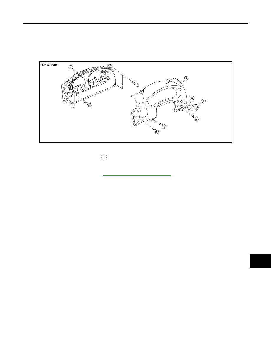
REMOVAL

1. Remove the cluster lid A. Refer to 

IP-14, "Removal and Installation"

.

2. Remove the combination meter screws, using power tool.
3. Pull out the combination meter and disconnect the combination meter harness connector.
4. Remove the combination meter.

INSTALLATION

Installation is in the reverse order of removal. 

1.

Combination meter

2.

Cluster lid A

3.

Ignition key lamp assembly

4.

Steering lock escutcheon

Metal clip

ALJIA0460ZZ

August 2012

2012 Pathfinder

PCS

PCS-1

ELECTRICAL & POWER CONTROL

C

D

E

F

G

H

I

J

K

L

B

SECTION 

PCS

A

O

P

N

CONTENTS

POWER  CONTROL SYSTEM

IPDM E/R

SYSTEM DESCRIPTION  ..............................

2

RELAY CONTROL SYSTEM  ..............................

2

System Diagram ........................................................

2

System Description  ...................................................

3

Component Parts Location ........................................

4

POWER CONTROL SYSTEM .............................

5

System Diagram ........................................................

5

System Description  ...................................................

5

SIGNAL BUFFER SYSTEM  ................................

6

System Diagram ........................................................

6

System Description  ...................................................

6

POWER CONSUMPTION CONTROL SYS-
TEM .....................................................................

7

System Diagram ........................................................

7

System Description  ...................................................

7

Component Parts Location ........................................

8

DIAGNOSIS SYSTEM (IPDM E/R) ......................

9

Diagnosis Description  ...............................................

9

CONSULT Function (IPDM E/R) .............................

11

DTC/CIRCUIT DIAGNOSIS  .........................

13

U1000 CAN COMM CIRCUIT .............................

13

Description ..............................................................

13

DTC Logic  ...............................................................

13

Diagnosis Procedure ...............................................

13

POWER SUPPLY AND GROUND CIRCUIT  ....

14

Diagnosis Procedure  ...............................................

14

ECU DIAGNOSIS INFORMATION ..............

15

IPDM E/R (INTELLIGENT POWER DISTRI-
BUTION MODULE ENGINE ROOM)  ................

15

Reference Value ......................................................

15

Terminal Layout .......................................................

16

Physical Values  .......................................................

17

Fail Safe ..................................................................

20

DTC Index ...............................................................

21

WIRING DIAGRAM ......................................

22

IPDM E/R (INTELLIGENT POWER DISTRI-
BUTION MODULE ENGINE ROOM)  ................

22

Wiring Diagram ........................................................

22

PRECAUTION ..............................................

27

PRECAUTIONS .................................................

27

Precaution for Supplemental Restraint System 
(SRS) "AIR BAG" and "SEAT BELT PRE-TEN-
SIONER" .................................................................

27

Precaution Necessary for Steering Wheel Rota-
tion After Battery Disconnect  ...................................

27

UNIT REMOVAL AND INSTALLATION ......

29

IPDM E/R (INTELLIGENT POWER DISTRI-
BUTION MODULE ENGINE ROOM)  ................

29

Removal and Installation of IPDM E/R  ....................

29

August 2012

2012 Pathfinder

PCS-2

< SYSTEM DESCRIPTION >

[IPDM E/R]

RELAY CONTROL SYSTEM

SYSTEM DESCRIPTION

RELAY CONTROL SYSTEM

System Diagram

INFOID:0000000007355013

AWMIA1249GB

August 2012

2012 Pathfinder

PCS

RELAY CONTROL SYSTEM

PCS-3

< SYSTEM DESCRIPTION >

[IPDM E/R]

C

D

E

F

G

H

I

J

K

L

B

A

O

P

N

System Description

INFOID:0000000007355014

IPDM E/R activates the internal control circuit to perform the relay ON-OFF control according to the input sig-

nals from various sensors and the request signals received from control units via CAN communication.

CAUTION:

IPDM E/R integrated relays cannot be removed.

Control relay

Input/output

Transmit unit

Control part

Reference 

page

Front fog lamp relay

Front fog lamp request signal

BCM (CAN)

Front fog lamps
(if equipped)

EXL-47

• Headlamp high relay
• Headlamp low relay

• High beam request signal
• Low beam request signal

BCM (CAN)

• Headlamp high
• Headlamp low

EXL-38
EXL-41

Tail lamp relay

Position light request signal

BCM (CAN)

• Parking lamps
• License plate lamps
• Tail  lamps
• Trailer tow relay
• Illumination system

EXL-49

• Front wiper relay
• Front wiper high relay

Front wiper request signal

BCM (CAN)

Front wiper motor

WW-4

Rear window defogger relay

Rear window defogger request signal

BCM (CAN)

Rear window defogger

DEF-4

A/C relay

A/C request signal

• BCM  (CAN)
• ECM  (CAN)

A/C compressor

HAC-69

Starter relay

Ignition switch START signal

TCM

Starter motor

STR-11

Cooling fan relay

Cooling fan request signal

ECM (CAN)

Cooling fan relay

CO-8

Heated mirror relay

Heated mirror request signal

BCM (CAN)

Door mirrors

DEF-14

ECM relay

ECM relay control signal

ECM (CAN)

ECM relay

EC-40

Throttle control motor relay

Throttle control motor control signal

ECM (CAN)

Throttle control motor relay

EC-48

Fuel pump relay

Fuel pump request signal

ECM (CAN)

Fuel pump

EC-406

Ignition relay

Ignition switch ON signal

Ignition switch

Ignition relay

EC-51

August 2012

2012 Pathfinder

PCS-4

< SYSTEM DESCRIPTION >

[IPDM E/R]

RELAY CONTROL SYSTEM

Component Parts Location

INFOID:0000000007355015

1.

IPDM E/R E118, E119, E120, E121, 
E122, E123, E124

ALMIA0310ZZ

August 2012

2012 Pathfinder

PCS

POWER CONTROL SYSTEM

PCS-5

< SYSTEM DESCRIPTION >

[IPDM E/R]

C

D

E

F

G

H

I

J

K

L

B

A

O

P

N

POWER CONTROL SYSTEM

System Diagram

INFOID:0000000007355016

System Description

INFOID:0000000007355017

COOLING FAN CONTROL

IPDM E/R controls the cooling fan according to the status of the cooling fan speed request signal received

from ECM via CAN communication. Refer to 

LAN-52, "CAN System Specification Chart"

.

ALMIA0111GB

August 2012

2012 Pathfinder

PCS-6

< SYSTEM DESCRIPTION >

[IPDM E/R]

SIGNAL BUFFER SYSTEM

SIGNAL BUFFER SYSTEM

System Diagram

INFOID:0000000007355018

System Description

INFOID:0000000007355019

IPDM E/R reads the status of the oil pressure switch and transmits the oil pressure switch signal to BCM via

CAN communication. Refer to 

BCS-12, "System Description"

.

AWNIA0174GB

August 2012

2012 Pathfinder

PCS

POWER CONSUMPTION CONTROL SYSTEM

PCS-7

< SYSTEM DESCRIPTION >

[IPDM E/R]

C

D

E

F

G

H

I

J

K

L

B

A

O

P

N

POWER CONSUMPTION CONTROL SYSTEM

System Diagram

INFOID:0000000007355020

System Description

INFOID:0000000007355021

OUTLINE

• IPDM E/R incorporates a power consumption control function that reduces the power consumption accord-

ing to the vehicle status. 

• IPDM E/R changes its status (control mode) with the sleep wake up signal received from BCM via CAN com-

munication.

Normal mode (wake-up)

- CAN communication is normally performed with other control units.

- Individual unit control by IPDM E/R is normally performed.

Low power consumption mode (sleep)

- Low power consumption control is active.

- CAN transmission is stopped.

SLEEP MODE ACTIVATION

• IPDM E/R judges that the sleep-ready conditions are fulfilled when the ignition switch is OFF and none of the

conditions below are present. Then it transmits a sleep-ready signal (ready) to BCM via CAN communica-

tion.

- Front wiper fail-safe operation 

- Outputting signals to actuators

- Switches or relays operating

- Auto active test is starting

- Emergency OFF

- Output requests are being received from control units via CAN communication.

• IPDM E/R stops CAN communication and enters the low power consumption mode when it receives a sleep

wake up signal (sleep) from BCM and the sleep-ready conditions are fulfilled.

WAKE-UP OPERATION

• IPDM E/R changes from the low power consumption mode to the normal mode when it receives a sleep

wake-up signal (wake up) from BCM or any of the following conditions is fulfilled. In addition, it transmits a

sleep-ready signal (not-ready) to BCM via CAN communication to report the CAN communication start.

- Ignition switch ON

- An output request is received from a control unit via CAN communication.

ALCIA0030GB

August 2012

2012 Pathfinder


Content      ..     481      482      483      484     ..