Nissan Pathfinder (2012 year). Manual - part 391


  Index      Manuals     Nissan Pathfinder (2012 year) - Service and Repair Manual


Search            copyright infringement  


Content      ..     389      390      391      392     ..


Nissan Pathfinder (2012 year). Manual - part 391


FSU-18

< UNIT REMOVAL AND INSTALLATION >

LOWER LINK

LOWER LINK

Removal and Installation

INFOID:0000000007357004

REMOVAL

1. Remove the wheel and tire using power tool.
2. Remove lower shock absorber bolt and nut using power tool.
3. Remove stabilizer bar connecting rod lower nut using power tool, then separate connecting rod from lower

link. Refer to 

FSU-16, "Removal and Installation"

.

4. For 4WD models, remove the drive shaft. Refer to 

FAX-7, "VQ40DE : Removal and Installation"

(VQ40DE) and  

FAX-8, "VK56DE : Removal and Installation"

 (VK56DE) procedures.

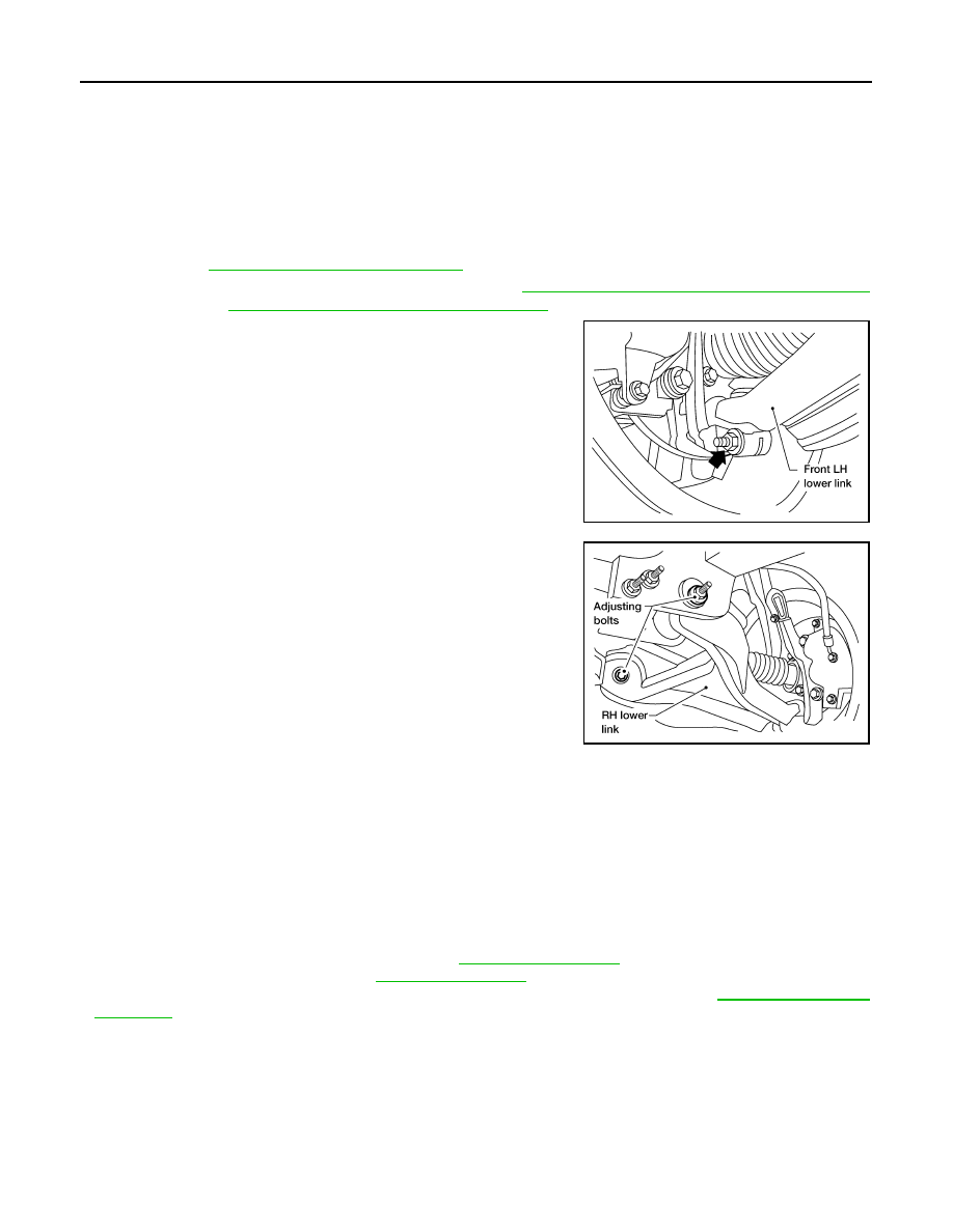
5. Remove pinch bolt from steering knuckle using power tool, then

separate lower link ball joint from steering knuckle.

6. Remove lower link adjusting bolts and nuts, then the lower link.

NOTE:

Some vehicles may be equipped with straight (non-adjustable)

lower link bolts and washers. In order to adjust camber and

caster on these vehicles, first replace the lower link bolts and

washers with adjustable (cam) bolts and washers.

7. Remove the jounce bumper from the lower link.

INSPECTION AFTER REMOVAL

Lower Link

Check for deformation and cracks. Replace if necessary.

Lower Link Bushing

Check for distortion and damage. Replace if necessary.

INSTALLATION

Installation is in the reverse order of removal.

• Tighten all nuts and bolts to specification. Refer to 

FSU-14, "Component"

.

• When installing wheel and tire, refer to 

WT-50, "Adjustment"

.

• After installation, check that the front wheel alignment is within specification. Refer to 

FSU-7, "Front Wheel

Alignment"

.

LEIA0097E

WEIA0115E

August 2012

2012 Pathfinder

UPPER BALL JOINT AND LOWER BALL JOINT

FSU-19

< UNIT REMOVAL AND INSTALLATION >

C

D

F

G

H

I

J

K

L

M

A

B

FSU

N

O

P

UPPER BALL JOINT AND LOWER BALL JOINT

Removal and Installation

INFOID:0000000007357005

The ball joints are part of the upper and lower links. Refer to 

FSU-17, "Removal and Installation"

 (upper link),

FSU-18, "Removal and Installation"

 (lower link). 

August 2012

2012 Pathfinder

FSU-20

< UNIT REMOVAL AND INSTALLATION >

KNUCKLE

KNUCKLE

Removal and Installation

INFOID:0000000007357006

REMOVAL

1. Remove wheel and tire from vehicle using power tool.
2. Remove the engine under cover using power tool (if equipped).
3. Without disassembling the hydraulic lines, remove brake caliper using power tool. Reposition it aside with

wire. Refer to 

BR-42, "Removal and Installation of Brake Caliper and Disc Rotor"

.

NOTE:

Avoid depressing brake pedal while brake caliper is removed.

4. Put alignment marks on disc rotor and wheel hub and bearing

assembly, then remove disc rotor.

5. Disconnect wheel sensor and remove bracket from steering knuckle.

CAUTION:

Do not pull on wheel sensor harness.

6. On 4WD models, remove cotter pin, then remove lock nut from drive shaft using power tool. Refer to 

FAX-7, "VQ40DE : Removal and Installation"

 (VQ40DE) and 

FAX-8, "VK56DE : Removal and Installation"

(VK56DE).

7. Remove steering outer socket cotter pin at steering knuckle, then loosen nut using power tool. Refer to

ST-31, "Disassembly and Assembly"

.

1.

Disc rotor

2.

Wheel hub and bearing assembly

3.

Wheel stud

4.

Splash guard

5.

Steering knuckle

6.

Wheel sensor bracket

WDIA0228E

WDIA0044E

August 2012

2012 Pathfinder

KNUCKLE

FSU-21

< UNIT REMOVAL AND INSTALLATION >

C

D

F

G

H

I

J

K

L

M

A

B

FSU

N

O

P

8. Disconnect steering outer socket from steering knuckle using

Tool. Be careful not to damage outer socket boot.

CAUTION:

To prevent damage to threads and to prevent Tool from

coming off suddenly, temporarily tighten nut. 

9. Remove wheel hub and bearing assembly bolts using power tool.
10. Remove splash guard and wheel hub and bearing assembly from steering knuckle.

CAUTION:

Do not pull on wheel sensor harness.

11. Remove cotter pin and nut from upper link ball joint.
12. Separate upper link ball joint from steering knuckle using Tool.

13. Remove pinch bolt from steering knuckle using power tool, then

separate lower link ball joint from steering knuckle.

14. Remove steering knuckle from vehicle.

INSPECTION AFTER REMOVAL

Check for deformity, cracks and damage on each part, replace if necessary.

• Perform ball joint inspection. Refer to 

FSU-11, "Inspection"

.

INSTALLATION

Installation is in the reverse order of removal.

• For 4WD models, refer to 

FAX-7, "VQ40DE : Removal and Installation"

 (VQ40DE) and 

FAX-8, "VK56DE :

Removal and Installation"

 (VK56DE) for drive shaft lock nut tightening torque.

CAUTION:

Always replace drive shaft lock nut and cotter pin.

• Refer to 

ST-31, "Disassembly and Assembly"

 for outer socket nut tightening torque.

• Refer to 

FSU-14, "Component"

 for front suspension tightening torques.

Tool number

: HT72520000 (J-25730-A)

SDIA1434E

Tool number

: ST29020001 (J-24319-01)

WEIA0119E

LEIA0097E

August 2012

2012 Pathfinder

FSU-22

< UNIT REMOVAL AND INSTALLATION >

KNUCKLE

• When installing disc rotor on wheel hub and bearing assembly,

align the marks.

NOTE:

When not using the alignment mark, refer to 

BR-42, "Removal and

Installation of Brake Caliper and Disc Rotor"

.

• When installing wheel and tire, refer to 

WT-50, "Adjustment"

.

• Perform wheel alignment. Refer to 

FSU-7, "Front Wheel Align-

ment"

.

WDIA0044E

August 2012

2012 Pathfinder

COIL SPRING AND SHOCK ABSORBER

FSU-23

< UNIT DISASSEMBLY AND ASSEMBLY >

C

D

F

G

H

I

J

K

L

M

A

B

FSU

N

O

P

UNIT DISASSEMBLY AND ASSEMBLY

COIL SPRING AND SHOCK ABSORBER

Disassembly and Assembly

INFOID:0000000007357007

DISASSEMBLY

1. Set the shock absorber in a vise, then loosen (without removing)

the piston rod lock nut as shown.

CAUTION:

Do not remove piston rod lock nut at this time.

2. Compress the coil spring using commercial service tool until the

shock absorber mounting insulator can be turned by hand.

WARNING:

Make sure that the pawls of the two spring compressors are

firmly hooked on the coil spring. The spring compressors

must be tightened alternately and evenly so as not to tilt the

coil spring.

3. Remove the piston rod lock nut.

• Discard the piston rod lock nut, use a new nut for assembly.

4. Remove the components from the shock absorber.

• Keep the coil spring compressed in the commercial service

tool if reusing it for assembly.

INSPECTION AFTER DISASSEMBLY

Shock Absorber Assembly

• Check for smooth operation through a full stroke, both compression and extension.

• Check for oil leakage on welded or gland packing portions.

• Check piston rod for cracks, deformation or other damage and replace if necessary.

Mounting Insulator and Rubber Parts

Check cemented rubber-to-metal portion for separation or cracks. Check rubber parts for deterioration and

replace if necessary.

Coil Spring

• Check for cracks, deformation or other damage and replace if necessary.

• Check the coil spring free height.

ASSEMBLY

SSU002

SSU003

Front spring free height
2WD

: Refer to 

FSU-25, "Spring Free Height"

.

4WD

: Refer to 

FSU-25, "Spring Free Height"

.

August 2012

2012 Pathfinder

FSU-24

< UNIT DISASSEMBLY AND ASSEMBLY >

COIL SPRING AND SHOCK ABSORBER

1. When installing coil spring on strut, it must be positioned as

shown.

2. Install the shock absorber mounting insulator as shown in line

with lower shock mount and step in lower seat.

• The step in the strut assembly lower seat faces outside of

vehicle.

3. Tighten the new piston rod lock nut to specification. Refer to

FSU-14, "Component"

.

• Use a new piston rod lock nut for assembly.

4. Remove commercial service tool.

SFA508A

WEIA0117E

August 2012

2012 Pathfinder

SERVICE DATA AND SPECIFICATIONS (SDS)

FSU-25

< SERVICE DATA AND SPECIFICATIONS (SDS) 

C

D

F

G

H

I

J

K

L

M

A

B

FSU

N

O

P

SERVICE DATA AND SPECIFICATIONS (SDS)

SERVICE DATA AND SPECIFICATIONS (SDS)

General Specification (Front)

INFOID:0000000007357008

Spring Free Height

INFOID:0000000007357009

Unit: mm (in)

Wheel Alignment (Unladen*1)

INFOID:0000000007357010

*1: Fuel, radiator coolant and engine oil full. Spare tire, jack, hand tools and mats in designated positions.

Suspension type

Independent double wishbone coil over shock

Shock absorber type

Double-acting hydraulic

Stabilizer

Standard equipment

Drive type

2WD

4WD

Front spring free height

345.4 (13.6)

356 (14.0)

Drive type

2WD

4WD

Camber
Degree minute (decimal degree)

Minimum

-0

°

 30

 (-0.50

°

)

-0

°

 15

 (-0.25

°

)

Nominal

0

°

 15

 (0.25

°

)

0

°

 30

 (0.50

°

)

Maximum

1

°

 00

 (1.00

°

)

1

°

 15

 (1.25

°

)

Cross camber

0

°

 45

 (0.75

°

) or less

 0

°

 45

 (0.75

°

) or less

Caster
Degree minute (decimal degree)

Minimum

2

°

 15

 (2.25

°

)

2

°

 00

 (2.00

°

)

Nominal

3

°

 0

 (3.00

°

)

2

°

 45

 (2.75

°

)

Maximum

3

°

 45

 (3.75

°

)

3

°

 30

 (3.50

°

)

Cross caster

0

°

 45

 (0.75

°

) or less

0

°

 45

 (0.75

°

) or less

Kingpin inclination
Degree minute (decimal degree)

Nominal

13

°

 0

 (13.00

°

)

12

°

 45

 (12.75

°

)

Total toe-in

Distance (A 

 B)

Minimum

In 1.2 mm (In 0.05 in)

In 1.2 mm (In 0.05 in)

Nominal

In 3.2 mm (In 0.12 in)

In 3.2 mm (In 0.12 in)

Maximum

In 5.2 mm (In 0.20 in)

In 5.2 mm (In 0.20 in)

Angle
Degree minute (decimal degree)

Minimum

In 0

°

 4

 48

 (In 0.08

°

)

In  0

°

 4

 48

 (In 0.08

°

)

Nominal

In 0

°

 14

 24

 In (0.24

°

)

In  0

°

 14

 24

 In (0.24

°

)

Maximum

In 0

°

 24

 (In 0.40

°

)

In  0

°

 24

 (In 0.40

°

)

Wheel turning angle (full turn)

Inside 
Degree minute (Decimal degree)

33

°

 26

– 35

°

 26

 *

2

(33.43

°

– 35.43

°

)

33

°

 33

– 35

°

 33

 *

4

(33.55

°

– 35.55

°

)

Outside
Degree minute (Decimal degree)

29

°

 22

– 31

°

 22

 *

3

(29.37

°

– 31.37

°

)

29

°

 38

– 31

°

 38

 *

5

(29.63

°

– 31.63

°

)

SFA234AC

August 2012

2012 Pathfinder


Content      ..     389      390      391      392     ..