Nissan Pathfinder (2012 year). Manual - part 390


  Index      Manuals     Nissan Pathfinder (2012 year) - Service and Repair Manual


Search            copyright infringement  


Content      ..     388      389      390      391     ..


Nissan Pathfinder (2012 year). Manual - part 390


FSU-10

< PERIODIC MAINTENANCE >

ON-VEHICLE SERVICE

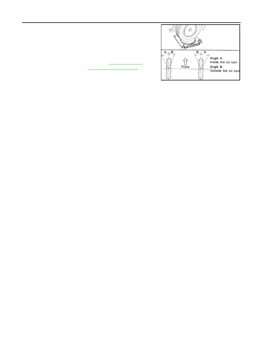
1. Place front wheels on turning radius gauges in straight ahead

position and rear wheels on stands so that vehicle can be level.

Check the maximum inner and outer wheel turning angles for LH

and RH road wheels.

2. Start engine and run at idle, turn steering wheel all the way right

and left, measure the turning angle.

• Any turning angles are not adjustable. If any of steering angles

are out of the specification, check if the following parts are

worn or damaged.

- Steering gear

- Steering column

- Front suspension components

If found that they are worn or damaged, replace them with new ones.

Wheel turning angle 
(full turn)

: Refer to 

FSU-25, "Wheel 

Alignment (Unladen*1)"

.

SFA439BA

August 2012

2012 Pathfinder

UPPER BALL JOINT AND LOWER BALL JOINT

FSU-11

< PERIODIC MAINTENANCE >

C

D

F

G

H

I

J

K

L

M

A

B

FSU

N

O

P

UPPER BALL JOINT AND LOWER BALL JOINT

Inspection

INFOID:0000000007356997

• Check the ball joint for excessive play. Replace the upper or lower link assembly if any of the following

exists:

- Ball joint stud is worn.

- Ball joint is hard to swing.

- Ball joint play in axial directions or end play is excessive.

SWINGING FORCE 

NOTE:

Before checking the axial forces and end play, turn the lower ball joint at least 10 revolutions so that the ball

joint is properly broken in.
1. Measure the ball joint swinging force using a suitable tool.

• Measure at the cotter pin hole for upper ball joint as shown.

• Measure at the groove for lower ball joint as shown.

2. Verify the ball joint swinging force is within specification.

TURNING FORCE

NOTE:

Before checking the axial forces and end play, turn the lower ball joint at least 10 revolutions so that the ball

joint is properly broken in.

VERTICAL END PLAY

Check dust cover for damage. Replace it and the cover clamp if necessary.

NOTE:

WEIA0076E

Swinging force (A)
(Measurement point at either cotter pin hole or groove 
of ball stud)
Upper

: Refer to 

FSU-26, "Ball Joint"

.

Lower : Refer to 

FSU-26, "Ball Joint"

.

SFA858A

Turning torque (B)
Upper

: Refer to 

FSU-26, "Ball Joint"

.

Lower

: Refer to 

FSU-26, "Ball Joint"

.

SFA858A

August 2012

2012 Pathfinder

FSU-12

< PERIODIC MAINTENANCE >

UPPER BALL JOINT AND LOWER BALL JOINT

Before checking the axial forces and end play, turn the lower ball

joint at least 10 revolutions so that the ball joint is properly broken in.

Vertical end play (C)

Refer to 

FSU-26, "Ball 

Joint"

.

SFA858A

August 2012

2012 Pathfinder

KNUCKLE

FSU-13

< PERIODIC MAINTENANCE >

C

D

F

G

H

I

J

K

L

M

A

B

FSU

N

O

P

KNUCKLE

On-Vehicle Inspection and Service

INFOID:0000000007356998

Make sure the mounting conditions (looseness, backlash) of each component and component status (wear,

damage) are within specifications. Refer to 

FSU-26, "Ball Joint"

.

August 2012

2012 Pathfinder

FSU-14

< REMOVAL AND INSTALLATION >

FRONT SUSPENSION ASSEMBLY

REMOVAL AND INSTALLATION

FRONT SUSPENSION ASSEMBLY

Component

INFOID:0000000007356999

1.

Dust cover

2.

Shock absorber

3.

Upper link

4.

Steering knuckle

5.

Cotter pin

6.

Washer

7.

Jounce bumper

8.

Bolt

9.

Lower link

10. Connecting rod

11. Stabilizer bar bushing

12. Stabilizer bar bracket

13. Stabilizer bar

14. Coil spring

15. Dust cover cap

16. Upper spring seat

17. Spacer

18. Shock absorber mounting insulator

19. Spacer

20. Washer

21. Cap

A.

To connecting rod

B.

To jounce bumper

Vehicle front

AWEIA0167GB

August 2012

2012 Pathfinder

COIL SPRING AND SHOCK ABSORBER

FSU-15

< UNIT REMOVAL AND INSTALLATION >

C

D

F

G

H

I

J

K

L

M

A

B

FSU

N

O

P

UNIT REMOVAL AND INSTALLATION

COIL SPRING AND SHOCK ABSORBER

Removal and Installation

INFOID:0000000007357000

REMOVAL

1. Remove the wheel and tire using power tool.
2. Support the lower link using a suitable jack.
3. Remove connecting rod upper joints from stabilizer bar using power tool. Refer to 

FSU-14, "Component"

.

• Swing stabilizer bar down, repositioning it out of the way to access shock absorber lower mount.

4. Remove the shock absorber lower bolt and nut using power tool.
5. Remove the three shock absorber upper mounting nuts using

power tool.

6. Remove the coil spring and shock absorber assembly.

• Turn steering knuckle out to gain enough clearance for

removal.

INSTALLATION

Installation is in the reverse order of removal.

• The step in the strut assembly lower seat faces outside of vehicle.

• Tighten all nuts and bolts to specification. Refer to 

FSU-14, "Component"

.

• When installing wheel and tire, refer to 

WT-50, "Adjustment"

.

Disposal

INFOID:0000000007357001

1. Set shock absorber horizontally with the piston rod fully extended.
2. Drill 2 – 3 mm (0.08 – 0.12 in) hole at the position ( ) from top

as shown in the figure to release gas gradually.

CAUTION:

• Wear eye protection (safety glasses).

• Wear gloves.

• Be careful with metal chips or oil blown out by the com-

pressed gas.

NOTE:

• Drill vertically in this direction (

).

• Directly to the outer tube avoiding brackets.

• The gas is clear, colorless, odorless, and harmless.

3. Position the drilled hole downward and drain oil by moving the piston rod several times.

CAUTION:

Dispose of drained oil according to the law and local regulations.

WEIA0116E

A

: 20 – 30 mm (0.79 – 1.18 in)

JPEIA0161ZZ

August 2012

2012 Pathfinder

FSU-16

< UNIT REMOVAL AND INSTALLATION >

STABILIZER BAR

STABILIZER BAR

Removal and Installation

INFOID:0000000007357002

REMOVAL

1. Remove the front valance center.
2. Remove engine under cover using power tool.
3. Remove connecting rod nuts using power tool.
4. Loosen top bolts for stabilizer bar brackets, then remove lower

bolts from brackets and remove stabilizer bar.

5. Remove bushings from stabilizer bar.

INSPECTION AFTER REMOVAL

• Check stabilizer bar for twist and deformation. Replace if necessary.

• Check rubber bushing for cracks, wear and deterioration. Replace if necessary.

INSTALLATION

Installation is in the reverse order of removal.

• Tighten all nuts and bolts to specification. Refer to 

FSU-14, "Component"

.

WEIA0118E

August 2012

2012 Pathfinder

UPPER LINK

FSU-17

< UNIT REMOVAL AND INSTALLATION >

C

D

F

G

H

I

J

K

L

M

A

B

FSU

N

O

P

UPPER LINK

Removal and Installation

INFOID:0000000007357003

REMOVAL

1. Remove the wheel and tire using power tool.
2. Support the lower link using a suitable jack.
3. For the LH side only, remove the pinch bolt from the lower joint

shaft at the steering gear, and position the lower joint shaft out of

the way.

CAUTION:

• Do not damage the lower joint.

4. Remove cotter pin and nut from upper link ball joint.
5. Separate upper link ball joint stud from steering knuckle using

Tool.

6. Remove upper link bolts and nuts.

INSPECTION AFTER REMOVAL

Upper Link

Check for deformation and cracks. Replace if necessary.

Upper Link Ball Joint

Check for distortion and damage. Replace if necessary.

INSTALLATION

Installation is in the reverse order of removal.

• Tighten all nuts and bolts to specification. Refer to 

FSU-14, "Component"

.

CAUTION:

Always replace drive shaft lock nut and cotter pin.

• When installing wheel and tire, refer to 

WT-50, "Adjustment"

.

• After installation, check that the front wheel alignment is within specification. Refer to 

FSU-7, "Front Wheel

Alignment"

.

LGIA0029E

Tool number

: ST29020001 (J-24319-01)

WEIA0119E

WEIA0120E

August 2012

2012 Pathfinder


Content      ..     388      389      390      391     ..