Nissan Pathfinder (2012 year). Manual - part 387
FUEL SYSTEM
FL-5
< PERIODIC MAINTENANCE >
C
D
E
F
G
H
I
J
K
L
M
A
FL
N
P
O
PERIODIC MAINTENANCE
FUEL SYSTEM
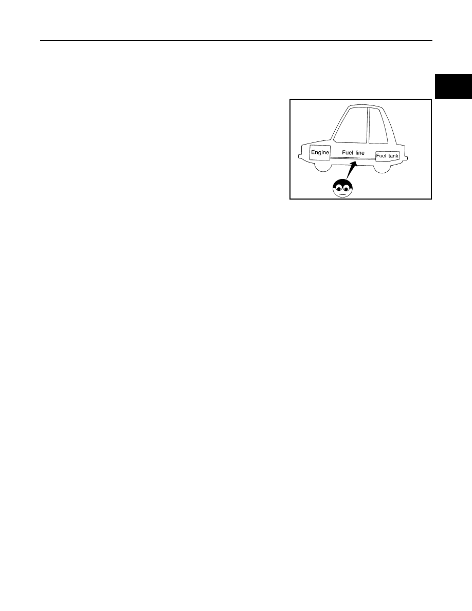
Checking Fuel Line
INFOID:0000000007358883
Inspect fuel lines, fuel filler cap and fuel tank for improper attach-
ment, leaks, cracks, damage, loose connections, chafing or deterio-
ration.
If necessary, repair or replace damaged parts.
SMA803A
August 2012
2012 Pathfinder