Nissan Pathfinder (2012 year). Manual - part 358


  Index      Manuals     Nissan Pathfinder (2012 year) - Service and Repair Manual


Search            copyright infringement  


Content      ..     356      357      358      359     ..


Nissan Pathfinder (2012 year). Manual - part 358


REFRIGERANT PRESSURE SENSOR

EC-945

< DTC/CIRCUIT DIAGNOSIS >

[VK56DE]

C

D

E

F

G

H

I

J

K

L

M

A

EC

N

P

O

Refer to 

EC-623, "Ground Inspection"

.

OK or NG

OK

>> GO TO 3.

NG

>> Repair or replace ground connections.

3.

CHECK REFRIGERANT PRESSURE SENSOR POWER SUPPLY CIRCUIT

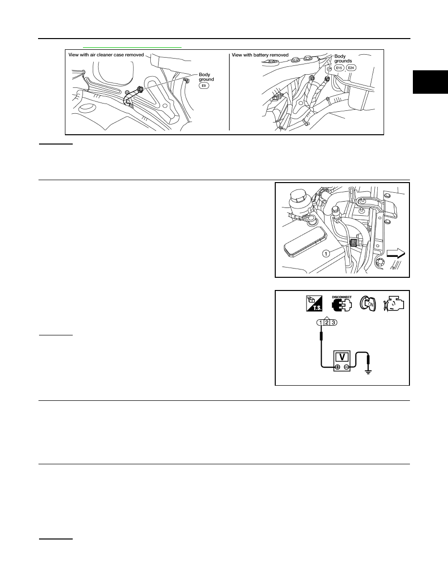
1. Disconnect refrigerant pressure sensor (1) harness connector.

2. Turn ignition switch ON.

3. Check voltage between refrigerant pressure sensor terminal 1

and ground with CONSULT or tester.

OK or NG

OK

>> GO TO 5.

NG

>> GO TO 4.

4.

DETECT MALFUNCTIONING PART

Check the following.

• Harness connectors E5, F14

• Harness for open or short between ECM and refrigerant pressure sensor

>> Repair harness or connectors.

5.

CHECK REFRIGERANT PRESSURE SENSOR GROUND CIRCUIT FOR OPEN AND SHORT

1. Turn ignition switch OFF.

2. Disconnect ECM harness connector.

3. Check harness continuity between refrigerant pressure sensor terminal 3 and ECM terminal 67.

Refer to Wiring Diagram.

4. Also check harness for short to ground and short to power.
OK or NG

OK

>> GO TO 7.

NG

>> GO TO 6.

BBIA0539E

ALBIA0357ZZ

Voltage: Approximately 5 V

PBIB0188E

Continuity should exist.

August 2012

2012 Pathfinder

EC-946

< DTC/CIRCUIT DIAGNOSIS >

[VK56DE]

REFRIGERANT PRESSURE SENSOR

6.

DETECT MALFUNCTIONING PART

Check the following.

• Harness connectors E5, F14

• Harness for open or short between ECM and refrigerant pressure sensor

>> Repair open circuit or short to ground or short to power in harness or connectors.

7.

CHECK REFRIGERANT PRESSURE SENSOR INPUT SIGNAL CIRCUIT FOR OPEN AND SHORT

1. Check harness continuity between ECM terminal 70 and refrigerant pressure sensor terminal 2.

Refer to Wiring Diagram.

2. Also check harness for short to ground and short to power.
OK or NG

OK

>> GO TO 9.

NG

>> GO TO 8.

8.

DETECT MALFUNCTIONING PART

Check the following.

• Harness connectors E5, F14

• Harness for open or short between ECM and refrigerant pressure sensor

>> Repair open circuit or short to ground or short to power in harness or connectors.

9.

CHECK INTERMITTENT INCIDENT

Refer to 

GI-37, "Intermittent Incident"

.

OK or NG

OK

>> Replace refrigerant pressure sensor. Refer to 

HA-54

.

NG

>> Repair or replace malfunctioning part.

Continuity should exist.

August 2012

2012 Pathfinder

ENGINE CONTROL SYSTEM SYMPTOMS

EC-947

< SYMPTOM DIAGNOSIS >

[VK56DE]

C

D

E

F

G

H

I

J

K

L

M

A

EC

N

P

O

SYMPTOM DIAGNOSIS

ENGINE CONTROL SYSTEM SYMPTOMS

Symptom Matrix Chart

INFOID:0000000007358861

SYSTEM — BASIC ENGINE CONTROL SYSTEM

SYMPTOM

Refer-
ence page

HARD/NO ST

AR

T

/REST

AR

T

 (EXCP

H

A

)

ENGINE ST

ALL

HESIT

A

TION/SURGING/FLA

T

 SPOT

SP

ARK KNOCK/DET

O

NA

TION

LACK

 OF POWER/

POOR 

ACC

E

LERA

TION

HIGH IDL

E/LOW

 IDLE

ROUG

H IDLE/HUNTING

IDLI

NG VIBRA

TION

SLOW

/NO RETURN T

O

 IDLE

OVERHEA

T

S/W

A

TER TEMPERA

T

UR

E

 HIGH

EXCESS

IVE F

U

E

L CONSUMP

T

IO

N

EXCESS

IVE OIL CONSUMP

T

ION

BA

TTER

Y

 DEAD (UNDER CHARGE)

Warranty symptom code

AA

AB

AC

AD

AE

AF AG AH

AJ

AK

AL

AM HA

Fuel

Fuel  pump  circuit

1

1

2

3

2

2

2

3

2

EC-928

Fuel  pressure  regulator  system

3

3

4

4

4

4

4

4

4

4

EC-952

Fuel  injector  circuit

1

1

2

3

2

2

2

2

EC-925

Evaporative  emission  system

3

3

4

4

4

4

4

4

4

4

EC-516

Air

Positive crankcase ventilation sys-
tem

3

3

4

4

4

4

4

4

4

4

1

EC-942

Incorrect idle speed adjustment

1

1

1

1

1

EC-592

Electric  throttle  control  actuator

1

1

2

3

3

2

2

2

2

2

2

EC-885
EC-888
EC-892
EC-894

Ignition

Incorrect  ignition  timing  adjustment

3

3

1

1

1

1

1

1

EC-592

Ignition  circuit

1

1

2

2

2

2

2

2

EC-931

Main  power  supply  and  ground  circuit

2

2

3

3

3

3

3

2

3

EC-620

August 2012

2012 Pathfinder

EC-948

< SYMPTOM DIAGNOSIS >

[VK56DE]

ENGINE CONTROL SYSTEM SYMPTOMS

1 - 6: The numbers refer to the order of inspection.
(continued on next table)

SYSTEM — ENGINE MECHANICAL & OTHER

Mass air flow sensor circuit

1

1

2

2

2

2

2

2

EC-643
EC-647

Engine coolant temperature sensor circuit

3

3

3

EC-657
EC-661

Air fuel ratio (A/F) sensor 1 circuit

EC-676
EC-680
EC-684
EC-688
EC-911

Throttle position sensor circuit

2

2

EC-664
EC-731
EC-853
EC-855
EC-903

Accelerator pedal position sensor circuit

3

2

1

EC-836
EC-896
EC-899
EC-907

Knock sensor circuit

2

3

EC-742

Crankshaft position sensor (POS) circuit

2

2

EC-745

Camshaft position sensor (PHASE) circuit

3

2

EC-749

Vehicle speed signal circuit

2

3

3

3

EC-820

Power steering pressure sensor circuit

2

3

3

EC-828

ECM

2

2

3

3

3

3

3

3

3

3

3

EC-831
EC-833
EC-835

Intake valve timing control solenoid valve cir-
cuit

3

2

1

3

2

2

3

3

EC-640

Park/neutral position (PNP) signal circuit

3

3

3

3

3

EC-839

Refrigerant pressure sensor circuit

2

3

3

4

EC-944

Electrical load signal circuit

3

EC-923

Air  conditioner  circuit

2

2

3

3

3

3

3

3

3

3

2

HAC-4

 or 

HAC-128

ABS actuator and electric unit (control unit)

4

EC-848

SYMPTOM

Refer-
ence page

HARD/NO S

TA

R

T/RES

TA

R

T (E

XCP

. HA)

E

N

GINE

 ST

ALL

HES

IT

A

TION/SURGING/FLA

T

 SPOT

S

P

ARK KNOC

K

/DET

O

NA

TI

ON

LACK OF 

POWER/POOR ACCELERA

TION

HIG

H

 IDL

E

/L

OW

 ID

LE

ROUGH IDLE/HUNTING

ID

LING VI

BRA

T

ION

S

LOW/NO RETU

RN 

T

O ID

LE

OVERHEA

T

S

/W

A

TER TEMPERA

T

URE HIG

H

E

XCESSIVE

 FUEL CON

S

UMP

T

ION

E

XCESSIVE

 OIL 

C

O

NSUMP

T

ION

B

A

TTER

DEAD (UNDER CHARGE)

Warranty symptom code

AA

AB

AC

AD

AE

AF AG AH

AJ

AK

AL

AM HA

August 2012

2012 Pathfinder

ENGINE CONTROL SYSTEM SYMPTOMS

EC-949

< SYMPTOM DIAGNOSIS >

[VK56DE]

C

D

E

F

G

H

I

J

K

L

M

A

EC

N

P

O

SYMPTOM

Reference 
page

HARD/NO ST

AR

T/REST

AR

T (EXCP

HA)

E

N

GI

N

E

 ST

AL

L

HESIT

A

TION/S

U

R

GING/F

LA

T SP

OT

SP

ARK KNOCK/DE

T

O

NA

TION

LACK OF POWE

R/POOR

 ACCELERA

TIO

N

HIGH IDL

E/L

OW

 IDL

E

ROUG

H IDLE/HU

NTING

IDL

ING VIBRA

T

ION

SLO

W

/NO RETURN T

O

 IDLE

OVERHEA

T

S/W

A

TE

R

 TEMPERA

T

URE 

HIGH

EXCES

SIVE F

U

EL CONSUMP

T

ION

EXCES

SIVE OI

L CONSUMP

T

IO

N

BA

TTE

R

DEAD (UN

D

E

R

 CH

A

R

GE)

Warranty symptom code

AA

AB

AC

AD

AE

AF

AG AH

AJ

AK

AL

AM HA

Fuel

Fuel tank

5

5

FL-6

Fuel piping

5

5

5

5

5

5

FL-5

Vapor lock

Valve deposit

5

5

5

5

5

5

5

Poor fuel (Heavy weight gasoline, 
Low octane)

Air

Air duct

5

5

5

5

5

5

EM-164

Air cleaner

EM-164

Air leakage from air duct
(Mass air flow sensor — electric 
throttle control actuator)

5

5

5

5

EM-164

Electric throttle control actuator

EM-165

Air leakage from intake manifold/
Collector/Gasket

EM-165

Cranking

Battery

1

1

1

1

1

1

1

1

PG-5

Generator circuit

CHG-5

CHG-8

Starter circuit

3

STR-5

STR-9

Signal plate

6

EM-199

Park/neutral position (PNP) sig-
nal

4

TM-51

Engine

Cylinder head

5

5

5

5

5

5

5

5

EM-214

Cylinder head gasket

4

3

Cylinder block

6

6

6

6

6

6

6

6

4

EM-228

Piston

Piston ring

Connecting rod

Bearing

Crankshaft

August 2012

2012 Pathfinder

EC-950

< SYMPTOM DIAGNOSIS >

[VK56DE]

ENGINE CONTROL SYSTEM SYMPTOMS

1 - 6: The numbers refer to the order of inspection.

Valve 
mecha-
nism

Timing chain

5

5

5

5

5

5

5

5

EM-194

Camshaft

EM-199

Intake valve timing control

EM-194

Intake valve

3

EM-214

Exhaust valve

Exhaust

Exhaust manifold/Tube/Muffler/
Gasket

5

5

5

5

5

5

5

5

EM-169

Three way catalyst

Lubrica-
tion

Oil pan/Oil strainer/Oil pump/Oil 
filter/Oil gallery/Oil cooler

5

5

5

5

5

5

5

5

LU-29
LU-30
LU-32
LU-34

Oil level (Low)/Filthy oil

LU-26

Cooling

Radiator/Hose/Radiator filler cap

5

5

5

5

5

5

5

4

5

CO-41

Thermostat

5

CO-54

Water pump

CO-52

Water gallery

CO-37

Cooling fan

5

CO-49
CO-50

Coolant level (Low)/Contaminat-
ed coolant

5

CO-41

NVIS (NISSAN Vehicle Immobilizer System — 
NATS)

1

1

SEC-5

 or 

SEC-116

SYMPTOM

Reference 
page

HARD/NO S

TA

R

T/RES

TA

R

T (E

XCP

. HA)

E

N

GINE

 ST

ALL

HES

IT

A

TION/SURGING/FLA

T

 SPOT

S

P

ARK KNOC

K

/DET

O

NA

TI

ON

LACK OF 

POWER/POOR ACCELERA

TION

HIG

H

 IDL

E

/L

OW

 ID

LE

ROUGH IDLE/HUNTING

ID

LING VI

BRA

T

ION

S

LOW/NO RETU

RN 

T

O ID

LE

OVERHEA

T

S

/W

A

TER TEMPERA

T

URE HIG

H

E

XCESSIVE

 FUEL CON

S

UMP

T

ION

E

XCESSIVE

 OIL 

C

O

NSUMP

T

ION

B

A

TTER

DEAD (UNDER CHARGE)

Warranty symptom code

AA

AB

AC

AD

AE

AF

AG AH

AJ

AK

AL

AM HA

August 2012

2012 Pathfinder

NORMAL OPERATING CONDITION

EC-951

< SYMPTOM DIAGNOSIS >

[VK56DE]

C

D

E

F

G

H

I

J

K

L

M

A

EC

N

P

O

NORMAL OPERATING CONDITION

Fuel Cut Control (at No Load and High Engine Speed)

INFOID:0000000007358862

INPUT/OUTPUT SIGNAL CHART

*: This signal is sent to the ECM via the CAN communication line.

SYSTEM DESCRIPTION

If the engine speed is above 2,400 rpm under no load (for example, the selector lever position is neutral and

engine speed over is 2,400 rpm) fuel will be cut off after some time. The exact time when the fuel is cut off var-

ies based on engine speed.

Fuel cut will be operated until the engine speed reaches 1,000 rpm, then fuel cut will be cancelled.

NOTE:

This function is different from deceleration control listed under 

EC-507, "System Description"

.

Sensor

Input signal to ECM

ECM function

Actuator

Accelerator pedal position sensor

Accelerator pedal position

Fuel cut control Fuel injector

Engine coolant temperature sensor

Engine coolant temperature

Crankshaft position sensor (POS)
Camshaft position sensor (PHASE)

Engine speed

Unified meter control unit

Neutral position

Vehicle speed*

August 2012

2012 Pathfinder

EC-952

< PERIODIC MAINTENANCE >

[VK56DE]

FUEL PRESSURE

PERIODIC MAINTENANCE

FUEL PRESSURE

Fuel Pressure Check

INFOID:0000000007358863

FUEL PRESSURE RELEASE

 With CONSULT

1. Turn ignition switch ON.
2. Perform “FUEL PRESSURE RELEASE” in “WORK SUPPORT” mode with CONSULT.
3. Start engine.
4. After engine stalls, crank it 2 or 3 times to release all fuel pressure.
5. Turn ignition switch OFF.

 Without CONSULT

1. Remove fuel pump fuse (1) located in IPDM E/R (2).
2. Start engine.
3. After engine stalls, crank it 2 or 3 times to release all fuel pres-

sure.

4. Turn ignition switch OFF.
5. Reinstall fuel pump fuse after servicing fuel system.

FUEL PRESSURE CHECK

CAUTION:

• Before disconnecting fuel line, release fuel pressure from fuel line to eliminate danger.

• Be careful not to scratch or get the fuel hose connection area dirty when servicing, so that the quick

connector o-ring maintains seal ability.

• Use Fuel Pressure Gauge Kit [SST (J-44321)] and Fuel Pressure Adapter [SST (J-44321-6)] to check

fuel pressure.

• Never perform fuel pressure check with electrical system operating (i.e. lights, rear window defog-

ger, A/C, etc.). Fuel pressure gauge may indicate false readings due to varying engine loads and

changes in manifold vacuum.

NOTE:

Prepare pans or saucers under the disconnected fuel line because the fuel may spill out. The fuel pres-

sure cannot be completely released because R51 models do not have fuel return system.

1. Release fuel pressure to zero. Refer to "FUEL PRESSURE RELEASE".
2. Remove engine cover.
3. Remove fuel hose using Quick Connector Release [SST (J-45488)]. Refer to 

EM-180, "Exploded View"

.

• Never twist or kink fuel hose because it is plastic hose.

• Never remove fuel hose from quick connector.

• Keep fuel hose connections clean.

4. Install Fuel Pressure Adapter [SST (J-44321-6)] and Fuel Pres-

sure Gauge [SST (J-44321)] (1) as shown in the figure.

• Never distort or bend fuel rail tube when installing fuel pres-

sure gauge adapter.

• When reconnecting fuel hose, check the original fuel hose for

damage and abnormality.

5. Turn ignition switch ON (reactivate fuel pump), and check for

fuel leakage.

6. Start engine and check for fuel leakage.
7. Read the indication of fuel pressure gauge.

ALBIA0351ZZ

ALBIA0367ZZ

August 2012

2012 Pathfinder


Content      ..     356      357      358      359     ..