Nissan Pathfinder (2012 year). Manual - part 356


  Index      Manuals     Nissan Pathfinder (2012 year) - Service and Repair Manual


Search            copyright infringement  


Content      ..     354      355      356      357     ..


Nissan Pathfinder (2012 year). Manual - part 356


FUEL PUMP

EC-929

< DTC/CIRCUIT DIAGNOSIS >

[VK56DE]

C

D

E

F

G

H

I

J

K

L

M

A

EC

N

P

O

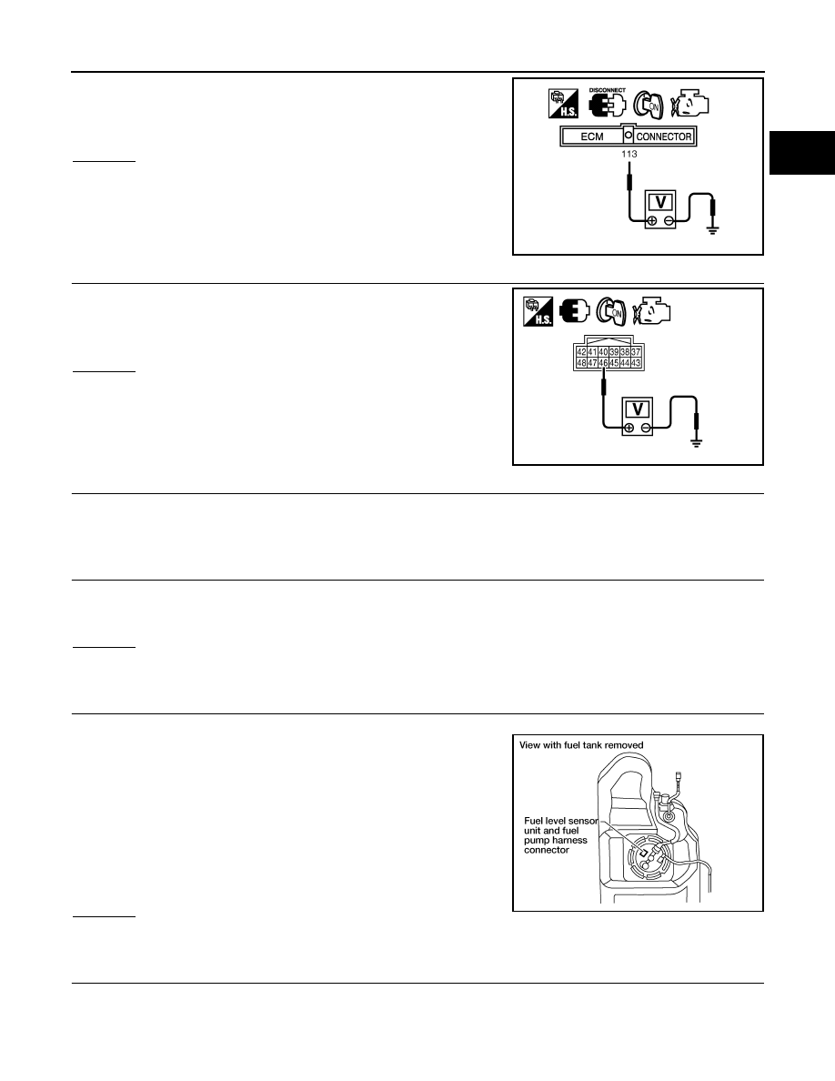
4. Check voltage between ECM terminal 113 and ground with

CONSULT or tester.

OK or NG

OK

>> GO TO 5.

NG

>> GO TO 3.

3.

CHECK FUEL PUMP POWER SUPPLY CIRCUIT-II

Check voltage between IPDM E/R terminal 46 and ground with

CONSULT or tester.

OK or NG

OK

>> GO TO 4.

NG

>> GO TO 9.

4.

DETECT MALFUNCTIONING PART

Check harness for open or short between IPDM E/R and ECM.

>> Repair harness or connectors.

5.

CHECK FUSE

1. Turn ignition switch OFF.

2. Disconnect 15 A fuse (No. 48).

3. Check 15 A fuse.
OK or NG

OK

>> GO TO 6.

NG

>> Replace fuse.

6.

CHECK FUEL PUMP POWER SUPPLY AND GROUND CIRCUIT FOR OPEN AND SHORT

1. Turn ignition switch OFF.

2. Disconnect “fuel level sensor unit and fuel pump” harness con-

nector.

3. Disconnect IPDM E/R harness connector E119.

4. Check harness continuity between IPDM E/R terminal 13 and

“fuel level sensor unit and fuel pump” terminal 1, “fuel level sen-

sor unit and fuel pump” terminal 3 and ground.

Refer to Wiring Diagram. 

5. Also check harness for short to ground and short to power.
OK or NG

OK

>> GO TO 8.

NG

>> GO TO 7.

7.

DETECT MALFUNCTIONING PART

Check the following.

• Harness connectors E41, C1

• Harness for open or short between fuel pump and IPDM E/R

Voltage: Battery voltage 

PBIB1187E

Voltage: Battery voltage

PBIB2656E

Continuity should exist.

BBIA0545E

August 2012

2012 Pathfinder

EC-930

< DTC/CIRCUIT DIAGNOSIS >

[VK56DE]

FUEL PUMP

• Harness for open or short between fuel pump and ground

>> Repair open circuit or short to ground or short to power in harness or connectors.

8.

CHECK FUEL PUMP

Refer to 

EC-930, "Component Inspection"

.

OK or NG

OK

>> GO TO 9.

NG

>> Replace “fuel level sensor unit and fuel pump”. Refer to 

FL-11

.

9.

CHECK INTERMITTENT INCIDENT

Refer to 

GI-37, "Intermittent Incident"

.

OK or NG

OK

>> Replace IPDM E/R. Refer to 

PCS-29

.

NG

>> Repair or replace harness or connectors.

Component Inspection

INFOID:0000000007358848

FUEL PUMP

1. Disconnect “fuel level sensor unit and fuel pump” harness connector.
2. Check resistance between fuel level sensor unit and fuel pump

terminals 1 and 3.

Resistance: 0.2 - 5.0 

 [at 25

°

C (77

°

F)]

SEC918C

August 2012

2012 Pathfinder

IGNITION SIGNAL

EC-931

< DTC/CIRCUIT DIAGNOSIS >

[VK56DE]

C

D

E

F

G

H

I

J

K

L

M

A

EC

N

P

O

IGNITION SIGNAL

Component Description

INFOID:0000000007358849

IGNITION COIL & POWER TRANSISTOR

The ignition signal from the ECM is sent to and amplified by the power transistor. The power transistor turns

ON and OFF the ignition coil primary circuit. This ON/OFF operation induces the proper high voltage in the coil

secondary circuit.

Diagnosis Procedure

INFOID:0000000007358850

1.

CHECK ENGINE START

Turn ignition switch OFF, and restart engine.

Is engine running?

Yes or No

Yes (With CONSULT)>>GO TO 2.

Yes (Without CONSULT)>>GO TO 3.

No

>> GO TO 4.

2.

CHECK OVERALL FUNCTION


With CONSULT

1. Perform “POWER BALANCE” in “ACTIVE TEST” mode with CONSULT.

2. Check that each circuit produces a momentary engine speed drop.
OK or NG

OK

>>

INSPECTION END

NG

>> GO TO 10.

3.

CHECK OVERALL FUNCTION

 Without CONSULT

1. Let engine idle.

2. Read the voltage signal between ECM terminals 46, 60, 61, 62,

65, 79, 80, 81 and ground with an oscilloscope.

3. Check that the oscilloscope screen shows the signal wave as

shown below.

NOTE:

The pulse cycle changes depending on rpm at idle.

1.

Ignition coils (with power transistor) 
(bank 2)

2.

Ignition coils (with power transistor) 
(bank 1)

: Vehicle front

ALBIA0370ZZ

PBIB2094E

PBIB0044E

August 2012

2012 Pathfinder

EC-932

< DTC/CIRCUIT DIAGNOSIS >

[VK56DE]

IGNITION SIGNAL

OK or NG

OK

>>

INSPECTION END

NG

>> GO TO 10.

4.

CHECK IGNITION COIL POWER SUPPLY CIRCUIT-I

1. Turn ignition switch OFF, wait at least 10 seconds and then turn it ON.

2. Check voltage between ECM terminals 119, 120 and ground

with CONSULT or tester.

OK or NG

OK

>> GO TO 5.

NG

>> Go to 

EC-620, "Diagnosis Procedure"

.

5.

CHECK IGNITION COIL POWER SUPPLY CIRCUIT-II

1. Turn ignition switch OFF.

2. Disconnect condenser-1 harness connector.

3. Turn ignition switch ON.

4. Check voltage between condenser-1 terminal 1 and ground with

CONSULT or tester.

OK or NG

OK

>> GO TO 8.

NG

>> GO TO 6.

6.

CHECK IGNITION COIL POWER SUPPLY CIRCUIT-III

1. Turn ignition switch OFF.

2. Disconnect IPDM E/R connector E119.

3. Check harness continuity between IPDM E/R terminal 3 and condenser-1 terminal 1.

Refer to Wiring Diagram.

4. Also check harness for short to ground and short to power.
OK or NG

OK

>> Go to 

EC-620, "Diagnosis Procedure"

.

NG

>> GO TO 7.

7.

DETECT MALFUNCTIONING PART

Check the following.

Voltage: Battery voltage

MBIB0034E

BBIA0358E

Voltage: Battery voltage

PBIB0624E

Continuity should exist.

August 2012

2012 Pathfinder

IGNITION SIGNAL

EC-933

< DTC/CIRCUIT DIAGNOSIS >

[VK56DE]

C

D

E

F

G

H

I

J

K

L

M

A

EC

N

P

O

• Harness connectors E2, F32

• IPDM E/R harness connector E119

• Harness for open or short between condenser-1 and IPDM E/R

>> Repair open circuit or short to ground or short to power in harness or connectors.

8.

CHECK CONDENSER-1 GROUND CIRCUIT FOR OPEN AND SHORT

1. Turn ignition switch OFF.

2. Check harness continuity between condenser-1 terminal 2 and ground.

Refer to Wiring Diagram.

3. Also check harness for short to power.
OK or NG

OK

>> GO TO 9.

NG

>> Repair open circuit or short to power in harness or connectors.

9.

CHECK CONDENSER-1

Refer to 

EC-934, "Component Inspection"

.

OK or NG

OK

>> GO TO 10.

NG

>> Replace condenser-1.

10.

CHECK IGNITION COIL POWER SUPPLY CIRCUIT-IV

1. Turn ignition switch OFF.

2. Reconnect all harness connectors disconnected.

3. Disconnect ignition coil harness connector.

4. Turn ignition switch ON.

5. Check voltage between ignition coil terminal 3 and ground with

CONSULT or tester.

OK or NG

OK

>> GO TO 12.

NG

>> GO TO 11.

11.

DETECT MALFUNCTIONING PART

Check the following.

Continuity should exist.

1.

Ignition coils (with power transistor) 
(bank 2)

2.

Ignition coils (with power transistor) 
(bank 1)

: Vehicle front

Voltage: Battery voltage

ALBIA0370ZZ

PBIB0138E

August 2012

2012 Pathfinder

EC-934

< DTC/CIRCUIT DIAGNOSIS >

[VK56DE]

IGNITION SIGNAL

• Harness connectors E2, F32

• Harness for open or short between ignition coil and harness connector F32

>> Repair or replace harness or connectors.

12.

CHECK IGNITION COIL GROUND CIRCUIT FOR OPEN AND SHORT

1. Turn ignition switch OFF.

2. Check harness continuity between ignition coil terminal 2 and ground.

Refer to Wiring Diagram.

3. Also check harness for short to power.
OK or NG

OK

>> GO TO 13.

NG

>> Repair open circuit or short to power in harness or connectors.

13.

CHECK IGNITION COIL OUTPUT SIGNAL CIRCUIT FOR OPEN AND SHORT

1. Disconnect ECM harness connector.

2. Check harness continuity between ECM terminals 46, 60, 61, 62, 65, 79, 80, 81 and ignition coil terminal

1.

Refer to Wiring Diagram.

3. Also check harness for short to ground and short to power.
OK or NG

OK

>> GO TO 14.

NG

>> Repair open circuit or short to ground or short to power in harness or connectors.

14.

CHECK IGNITION COIL WITH POWER TRANSISTOR

Refer to 

EC-934, "Component Inspection"

.

 OK or NG

OK

>> GO TO 15.

NG

>> Replace malfunctioning ignition coil with power transistor.

15.

CHECK INTERMITTENT INCIDENT

Refer to 

GI-37, "Intermittent Incident"

.

>>

INSPECTION END

Component Inspection

INFOID:0000000007358851

IGNITION COIL WITH POWER TRANSISTOR

CAUTION:

Perform the following procedure in a place with no combustible objects and good ventilation.

1. Turn ignition switch OFF.

2. Disconnect ignition coil harness connector.

3. Check resistance between ignition coil terminals as per the fol-

lowing.

4. If NG, replace ignition coil with power transistor. Refer to 

EM-

177

.

Continuity should exist.

Continuity should exist.

Terminal No. (Polarity)

Resistance [at 25

°

C (77

°

F)]

1 and 2

Except 0 or 


1 and 3

Except 0 

2 and 3

PBIB0847E

August 2012

2012 Pathfinder

IGNITION SIGNAL

EC-935

< DTC/CIRCUIT DIAGNOSIS >

[VK56DE]

C

D

E

F

G

H

I

J

K

L

M

A

EC

N

P

O

If OK, go to next step.

5. Turn ignition switch OFF.

6. Reconnect all harness connectors disconnected.

7. Remove fuel pump fuse (1) in IPDM E/R (2) to release fuel pres-

sure.

NOTE:

Do not use CONSULT to release fuel pressure, or fuel pressure

applies again during the following procedure.

8. Start engine.

9. After engine stalls, crank it 2 or 3 times to release all fuel pres-

sure.

10. Turn ignition switch OFF.

11. Remove all ignition coil harness connectors to avoid the electri-

cal discharge from the ignition coils.

12. Remove ignition coil and spark plug of the cylinder to be

checked. Refer to 

EM-177

.

13. Crank engine for 5 seconds or more to remove combustion gas in the cylinder.

14. Connect spark plug and harness connector to ignition coil.

15. Fix ignition coil using a rope etc. with gap of 13 - 17 mm

between the edge of the spark plug and grounded metal portion

as shown in the figure.

16. Crank engine for approximately 3 seconds, and check whether

spark is generated between the spark plug and the grounded

metal portion.

CAUTION:

• Never place the spark plug and the ignition coil within 50

cm each other. Be careful not to get an electrical shock

while checking, because the electrical discharge voltage

becomes 20 kV or more.

• It might damage the ignition coil if the gap of more than 17 mm is made.

NOTE:

When the gap is less than 13 mm, a spark might be generated even if the coil is malfunctioning.

17. If NG, replace ignition coil with power transistor. Refer to 

EM-177

.

CONDENSER-1

1. Turn ignition switch OFF.

2. Disconnect condenser-1 harness connector.

3. Check resistance between condenser-1 terminals 1 and 2.

Spark should be generated.

ALBIA0351ZZ

PBIB2325E

Resistance

Above 1 M

 at 25

°

C (77

°

F)

PBIB0794E

August 2012

2012 Pathfinder

EC-936

< DTC/CIRCUIT DIAGNOSIS >

[VK56DE]

MALFUNCTION INDICATOR LAMP

MALFUNCTION INDICATOR LAMP

Component Function Check

INFOID:0000000007358852

1.

CHECK MIL FUNCTION

1. Turn ignition switch ON.

2. Check that MIL illuminates.
Is the inspection result normal?

YES

>> INSPECTION END

NO

>> Proceed to 

EC-936, "Diagnosis Procedure"

.

Diagnosis Procedure

INFOID:0000000007358853

1.

CHECK DTC

Check that DTC UXXXX is not displayed.
Is the inspection result normal?

YES

>> GO TO 2.

NO

>> Perform trouble diagnosis for DTC UXXXX.

2.

CHECK DTC WITH COMBINATION METER

Refer to 

MWI-27, "CONSULT Function (METER/M&A)"

.

Is the inspection result normal?

YES

>> GO TO 3.

NO

>> Perform trouble diagnosis for DTC indicated.

3.

CHECK INTERMITTENT INCIDENT

Refer to 

GI-37, "Intermittent Incident"

.

Is the inspection result normal?

YES

>> Replace combination meter. Refer to 

MWI-89, "Removal and Installation"

.

NO

>> Repair or replace malfunctioning part.

August 2012

2012 Pathfinder


Content      ..     354      355      356      357     ..