Nissan Pathfinder (2012 year). Manual - part 354
P2A00, P2A03 A/F SENSOR 1
EC-913
< DTC/CIRCUIT DIAGNOSIS >
[VK56DE]
C
D
E
F
G
H
I
J
K
L
M
A
EC
N
P
O
EM-169, "Removal and Installation"
>> GO TO 3.
3.
CHECK FOR EXHAUST GAS LEAK
1. Start engine and run it at idle.
2. Listen for an exhaust gas leak before the three way catalyst 2.
Is exhaust gas leak detected?
YES
>> Repair or replace.
NO
>> GO TO 4.
4.
CHECK FOR INTAKE AIR LEAKAGE
1. Start engine and run it at idle.
2. Listen for an intake air leakage after the mass air flow sensor.
OK or NG
OK
>> GO TO 5.
NG
>> Repair or replace.
5.
CLEAR THE SELF-LEARNING DATA
With CONSULT
1. Start engine and warm it up to normal operating temperature.
2. Select “SELF-LEARNING CONT” in “WORK SUPPORT” mode with CONSULT.
3. Clear the self-learning control coefficient by touching “CLEAR”.
4. Run engine for at least 10 minutes at idle speed.
Is the 1st trip DTC P0171, P0172, P0174 or P0175 detected?
Is it difficult to start engine?
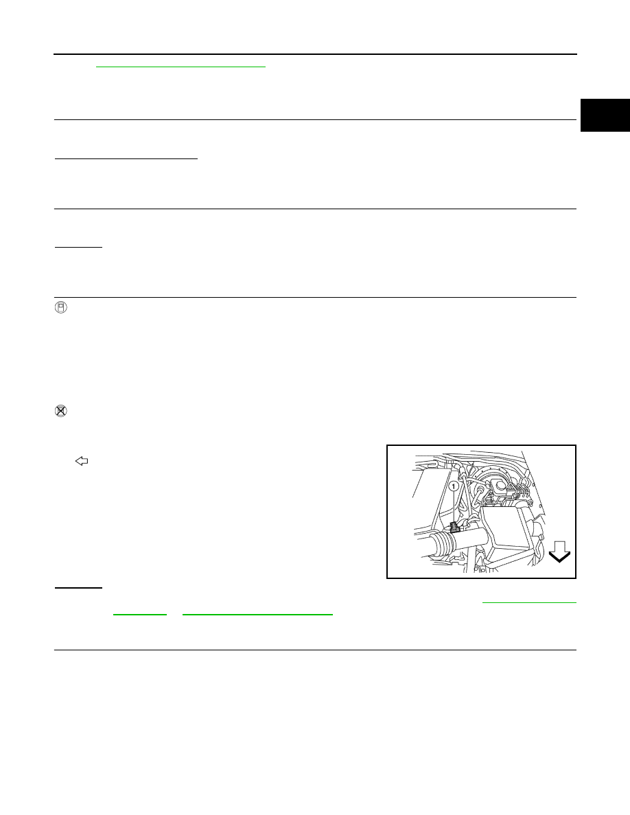
Without CONSULT
1. Start engine and warm it up to normal operating temperature.
2. Turn ignition switch OFF.
3. Disconnect mass air flow sensor (1) harness connector.
-
: Vehicle front
4. Restart engine and let it idle for at least 5 seconds.
5. Stop engine and reconnect mass air flow sensor harness con-
nector.
6. Check that DTC P0102 is displayed.
7. Erase the DTC memory.
8. Check that DTC P0000 is displayed.
9. Run engine for at least 10 minutes at idle speed.
Is the 1st trip DTC P0171, P0172, P0174 or P0175 detected?
Is it difficult to start engine?
Yes or No
Yes
>> Perform trouble diagnosis for DTC P0171, P0174 or P0172, P0175. Refer to
or
No
>> GO TO 6.
6.
CHECK HARNESS CONNECTOR
1. Turn ignition switch OFF.
2. Disconnect A/F sensor 1 harness connector.
ALBIA0353ZZ
August 2012
2012 Pathfinder