Nissan Pathfinder (2012 year). Manual - part 350


  Index      Manuals     Nissan Pathfinder (2012 year) - Service and Repair Manual


Search            copyright infringement  


Content      ..     348      349      350      351     ..


Nissan Pathfinder (2012 year). Manual - part 350


P1572 ASCD BRAKE SWITCH

EC-881

< DTC/CIRCUIT DIAGNOSIS >

[VK56DE]

C

D

E

F

G

H

I

J

K

L

M

A

EC

N

P

O

11.

CHECK INTERMITTENT INCIDENT

Refer to 

GI-37, "Intermittent Incident"

.

>>

INSPECTION END

Component Inspection

INFOID:0000000007358785
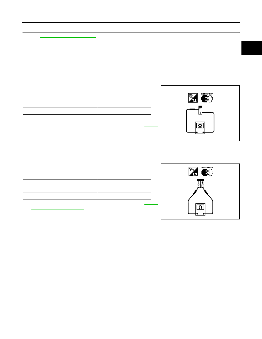
ASCD BRAKE SWITCH

1. Turn ignition switch OFF.
2. Disconnect ASCD brake switch harness connector.
3. Check harness continuity between ASCD brake switch terminals

1 and 2 under the following conditions.

If NG, adjust ASCD brake switch installation, refer to 

BR-23,

"Removal and Installation"

, and perform step 3 again.

STOP LAMP SWITCH

1. Turn ignition switch OFF.
2. Disconnect stop lamp switch harness connector.
3. Check harness continuity between stop lamp switch terminals 1

and 2 under the following conditions.

If NG, adjust stop lamp switch installation, refer to 

BR-23,

"Removal and Installation"

, and perform step 3 again.

Condition

Continuity

Brake pedal: Fully released

Should exist.

Brake pedal: Slightly depressed

Should not exist.

SEC023D

Condition

Continuity

Brake pedal: Fully released

Should not exist.

Brake pedal: Slightly depressed

Should exist.

PBIB1185E

August 2012

2012 Pathfinder

EC-882

< DTC/CIRCUIT DIAGNOSIS >

[VK56DE]

P1805 BRAKE SWITCH

P1805 BRAKE SWITCH

Description

INFOID:0000000007358786

Brake switch signal is applied to the ECM through the stop lamp switch when the brake pedal is depressed.

This signal is used mainly to decrease the engine speed when the vehicle is being driven.

On Board Diagnosis Logic

INFOID:0000000007358787

The MIL will not illuminate for this self-diagnosis.

FAIL-SAFE MODE

When the malfunction is detected, the ECM enters fail-safe mode.

DTC Confirmation Procedure

INFOID:0000000007358788

1. Turn ignition switch ON.
2. Fully depress the brake pedal for at least 5 seconds.
3. Erase the DTC.
4. Check 1st trip DTC.
5. If 1st trip DTC is detected, go to 

EC-882, "Diagnosis Procedure"

.

Diagnosis Procedure

INFOID:0000000007358789

1.

CHECK STOP LAMP SWITCH CIRCUIT

1. Turn ignition switch OFF.

2. Check the stop lamp when depressing and releasing the brake pedal.

OK or NG

OK

>> GO TO 4.

NG

>> GO TO 2.

2.

CHECK STOP LAMP SWITCH POWER SUPPLY CIRCUIT 

DTC No.

Trouble diagnosis name

DTC detecting condition

Possible cause

P1805
1805

Brake switch

A brake switch signal is not sent to ECM 
for extremely long time while the vehicle is 
being driven.

• Harness or connectors

(Stop lamp switch circuit is open or shorted.)

• Stop lamp switch

Engine operating condition in fail-safe mode

ECM controls the electric throttle control actuator by regulating the throttle opening to a small range.
Therefore, acceleration will be poor.

Vehicle condition

Driving condition

When engine is idling

Normal

When accelerating

Poor acceleration

Brake pedal

Stop lamp

Fully released

Not illuminated

Depressed

Illuminated

August 2012

2012 Pathfinder

P1805 BRAKE SWITCH

EC-883

< DTC/CIRCUIT DIAGNOSIS >

[VK56DE]

C

D

E

F

G

H

I

J

K

L

M

A

EC

N

P

O

1. Disconnect stop lamp switch harness connector.

2. Check voltage between stop lamp switch terminal 1 and ground

with CONSULT or tester.

OK or NG

OK

>> GO TO 4.

NG

>> GO TO 3.

3.

DETECT MALFUNCTIONING PART

Check the following.

• Fuse block (J/B) connector E160

• 10 A fuse (No. 20)

• Harness for open and short between stop lamp switch and fuse

>> Repair open circuit or short to ground or short to power in harness or connectors.

4.

CHECK STOP LAMP SWITCH INPUT SIGNAL CIRCUIT FOR OPEN AND SHORT

1. Turn ignition switch OFF.

2. Disconnect ECM harness connector.

3. Check harness continuity between ECM terminal 101 and stop lamp switch terminal 2.

Refer to Wiring Diagram.

4. Also check harness for short to ground and short to power.
OK or NG

OK

>> GO TO 5.

NG

>> Repair open circuit or short to ground or short to power in harness or connectors.

5.

CHECK STOP LAMP SWITCH 

Refer to 

EC-884, "Component Inspection"

.

OK or NG

OK

>> GO TO 6.

NG

>> Replace stop lamp switch. Refer to 

BR-22

.

6.

CHECK INTERMITTENT INCIDENT

Refer to 

GI-37, "Intermittent Incident"

.

>>

INSPECTION END

BBIA0560E

Voltage: Battery voltage

PBIB1184E

Continuity should exist.

August 2012

2012 Pathfinder

EC-884

< DTC/CIRCUIT DIAGNOSIS >

[VK56DE]

P1805 BRAKE SWITCH

Component Inspection

INFOID:0000000007358790

STOP LAMP SWITCH

1. Disconnect stop lamp switch harness connector.

2. Check continuity between stop lamp switch terminals 1 and 2

under the following conditions.

3. If NG, adjust stop lamp switch installation, refer to 

BR-23,

"Removal and Installation"

and perform step 2 again.

BBIA0560E

Conditions

Continuity

Brake pedal: Fully released

Should not exist.

Brake pedal: Slightly depressed

Should exist.

PBIB1185E

August 2012

2012 Pathfinder

P2100, P2103 THROTTLE CONTROL MOTOR RELAY

EC-885

< DTC/CIRCUIT DIAGNOSIS >

[VK56DE]

C

D

E

F

G

H

I

J

K

L

M

A

EC

N

P

O

P2100, P2103 THROTTLE CONTROL MOTOR RELAY

Component Description

INFOID:0000000007358791

Power supply for the throttle control motor is provided to the ECM via throttle control motor relay. The throttle

control motor relay is controlled ON/OFF by the ECM. When the ignition switch is turned ON, the ECM sends

an ON signal to throttle control motor relay and battery voltage is provided to the ECM. When the ignition

switch is turned OFF, the ECM sends an OFF signal to throttle control motor relay and battery voltage is not

provided to the ECM.

On Board Diagnosis Logic

INFOID:0000000007358792

These self-diagnoses have the one trip detection logic.

FAIL-SAFE MODE

When the malfunction is detected, ECM enters fail-safe mode and the MIL illuminates.

DTC Confirmation Procedure

INFOID:0000000007358793

NOTE:

If DTC Confirmation Procedure has been previously conducted, always perform the following procedure

before conducting the next step.

1. Turn ignition switch OFF and wait at least 10 seconds.

2. Turn ignition switch ON.

3. Turn ignition switch OFF and wait at least 10 seconds.

PROCEDURE FOR DTC P2100

1. Turn ignition switch ON and wait at least 2 seconds.
2. Start engine and let it idle for 5 seconds.
3. Check DTC.
4. If DTC is detected, go to 

EC-885, "Diagnosis Procedure"

.

PROCEDURE FOR DTC P2103 

TESTING CONDITION:

Before performing the following procedure, confirm that battery voltage is more than 8 V.

1. Turn ignition switch ON and wait at least 1 second.
2. Check DTC.
3. If DTC is detected, go to 

EC-885, "Diagnosis Procedure"

.

Diagnosis Procedure

INFOID:0000000007358794

1.

CHECK THROTTLE CONTROL MOTOR RELAY POWER SUPPLY CIRCUIT-I

1. Turn ignition switch OFF.

DTC No.

Trouble diagnosis name

DTC detecting condition

Possible cause

P2100
2100

Throttle control motor 
relay circuit open

ECM detects that the voltage of power 
source for throttle control motor is exces-
sively low.

• Harness or connectors

(Throttle control motor relay circuit is open)

• Throttle control motor relay

P2103
2103

Throttle control motor 
relay circuit short

ECM detects that the throttle control motor 
relay is stuck ON.

• Harness or connectors

(Throttle control motor relay circuit is shorted)

• Throttle control motor relay

Engine operating condition in fail-safe mode

ECM stops the electric throttle control actuator control, throttle valve is maintained at a fixed opening (approx. 5 degrees) by the return 
spring.

August 2012

2012 Pathfinder

EC-886

< DTC/CIRCUIT DIAGNOSIS >

[VK56DE]

P2100, P2103 THROTTLE CONTROL MOTOR RELAY

2. Check voltage between ECM terminal 104 and ground with

CONSULT or tester.

OK or NG

OK

>> GO TO 4.

NG

>> GO TO 2.

2.

CHECK THROTTLE CONTROL MOTOR RELAY POWER SUPPLY CIRCUIT-II

1. Disconnect ECM harness connector.

2. Disconnect IPDM E/R harness connector E122.

3. Check continuity between ECM terminal 104 and IPDM E/R terminal 47.

Refer to Wiring Diagram.

4. Also check harness for short to ground and short to power.
OK or NG

OK

>> GO TO 3.

NG

>> Repair open circuit or short to ground or short to power in harness or connectors.

3.

CHECK FUSE

1. Disconnect 20A fuse (No. 52).

2. Check 20 A fuse for blown.
OK or NG

OK

>> GO TO 7.

NG

>> Replace 20 A fuse.

4.

CHECK THROTTLE CONTROL MOTOR RELAY INPUT SIGNAL CIRCUIT-I

Check voltage between ECM terminal 3 and ground under the fol-

lowing conditions with CONSULT or tester.

OK or NG

OK

>> GO TO 7.

NG

>> GO TO 5.

5.

CHECK THROTTLE CONTROL MOTOR RELAY INPUT SIGNAL CIRCUIT-II

1. Turn ignition switch OFF.

2. Disconnect ECM harness connector.

3. Disconnect IPDM E/R harness connector E119.

4. Check continuity between ECM terminal 3 and IPDM E/R terminal 6.

Refer to Wiring Diagram.

5. Also check harness for short to ground and short to power.
OK or NG

OK

>> GO TO 7.

NG

>> GO TO 6.

Voltage: Battery voltage

PBIB1171E

Continuity should exist.

Ignition switch

Voltage

OFF

Approximately 0 V

ON

Battery voltage

(11 - 14 V)

MBIB0028E

Continuity should exist.

August 2012

2012 Pathfinder

P2100, P2103 THROTTLE CONTROL MOTOR RELAY

EC-887

< DTC/CIRCUIT DIAGNOSIS >

[VK56DE]

C

D

E

F

G

H

I

J

K

L

M

A

EC

N

P

O

6.

DETECT MALFUNCTIONING PART

Check the following.

• Harness connectors E2, F32

• Harness for open or short between ECM and IPDM E/R

>> Repair open circuit or short to ground or short to power in harness or connectors.

7.

CHECK INTERMITTENT INCIDENT

Refer to 

GI-37, "Intermittent Incident"

.

OK or NG

OK

>> Replace IPDM E/R. Refer to 

PCS-29, "Removal and Installation of IPDM E/R"

.

NG

>> Repair or replace harness or connectors.

August 2012

2012 Pathfinder

EC-888

< DTC/CIRCUIT DIAGNOSIS >

[VK56DE]

P2101 ELECTRIC THROTTLE CONTROL FUNCTION

P2101 ELECTRIC THROTTLE CONTROL FUNCTION

Description

INFOID:0000000007358795

NOTE:

If DTC P2101 is displayed with DTC P2100, first perform the trouble diagnosis for DTC P2100. Refer

to 

EC-885, "DTC Confirmation Procedure"

.

If DTC P2101 is displayed with DTC P2119, first perform the trouble diagnosis for DTC P2119. Refer

to 

EC-894, "DTC Confirmation Procedure"

.

Electric throttle control actuator consists of throttle control motor, throttle position sensor, etc.

The throttle control motor is operated by the ECM and it opens and closes the throttle valve.

The current opening angle of the throttle valve is detected by the throttle position sensor. The throttle position

sensor provides feedback to the ECM, when opens/closes the throttle valve in response to driving conditions

via the throttle control motor.

On Board Diagnosis Logic

INFOID:0000000007358796

This self-diagnosis has the one trip detection logic.

FAIL-SAFE MODE

When the malfunction is detected, ECM enters fail-safe mode and the MIL illuminates.

DTC Confirmation Procedure

INFOID:0000000007358797

NOTE:

If DTC Confirmation Procedure has been previously conducted, always perform the following procedure

before conducting the next step.

1. Turn ignition switch OFF and wait at least 10 seconds.

2. Turn ignition switch ON.

3. Turn ignition switch OFF and wait at least 10 seconds.

TESTING CONDITION:

Before performing the following procedure, confirm that battery voltage is more than 11 V when

engine is running.

1. Turn ignition switch ON and wait at least 2 seconds.
2. Start engine and let it idle for 5 seconds.
3. Check DTC.
4. If DTC is detected, go to 

EC-888, "Diagnosis Procedure"

.

Diagnosis Procedure

INFOID:0000000007358798

1.

CHECK GROUND CONNECTIONS

1. Turn ignition switch OFF.

2. Loosen and retighten ground screws on the body.

DTC No.

Trouble diagnosis name

DTC detecting condition

Possible cause

P2101
2101

Electric throttle control 
performance

Electric throttle control function does not 
operate properly.

• Harness or connectors

(Throttle control motor circuit is open or shorted)

• Electric throttle control actuator

Engine operating condition in fail-safe mode

ECM stops the electric throttle control actuator control, throttle valve is maintained at a fixed opening (approx. 5 degrees) by the return 
spring.

August 2012

2012 Pathfinder


Content      ..     348      349      350      351     ..