Nissan Pathfinder (2012 year). Manual - part 349
P1564 ASCD STEERING SWITCH
EC-873
< DTC/CIRCUIT DIAGNOSIS >
[VK56DE]
C
D
E
F
G
H
I
J
K
L
M
A
EC
N
P
O
P1564 ASCD STEERING SWITCH
Component Description
INFOID:0000000007358776
ASCD steering switch has variant values of electrical resistance for each button. ECM reads voltage variation
of switch, and determines which button is operated.
On Board Diagnosis Logic
INFOID:0000000007358777
•
This self-diagnosis has the one trip detection logic.
•
The MIL will not illuminate for this self-diagnosis.
NOTE:
If DTC P1564 is displayed with DTC P0605, first perform the trouble diagnosis for DTC P0605. Refer to
EC-836, "DTC Confirmation Procedure"
.
DTC Confirmation Procedure
INFOID:0000000007358778
1. If DTC Confirmation Procedure has been previously conducted, always perform the following procedure
before conducting the next step.
a. Turn ignition switch OFF and wait at least 10 seconds.
b. Turn ignition switch ON.
c. Turn ignition switch OFF and wait at least 10 seconds.
2. Turn ignition switch ON and wait at least 10 seconds.
3. Press MAIN switch for at least 10 seconds, then release it and wait at least 10 seconds.
4. Press CANCEL switch for at least 10 seconds, then release it and wait at least 10 seconds.
5. Press RESUME/ACCELERATE switch for at least 10 seconds, then release it and wait at least 10 sec-
onds.
6. Press SET/COAST switch for at least 10 seconds, then release it and wait at least 10 seconds.
7. Check DTC.
8. If DTC is detected, go to
.
Diagnosis Procedure
INFOID:0000000007358779
1.
CHECK GROUND CONNECTIONS
1.
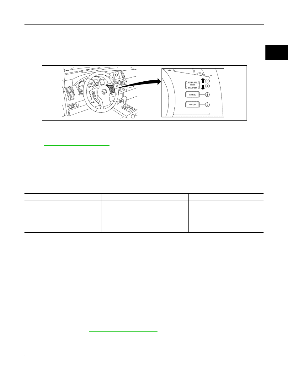
ASCD steering switch
2.
MAIN switch
3.
CANCEL switch
4.
SET/COAST switch
5.
RESUME/ACCELERATE switch
ALBIA0364ZZ
DTC No.
Trouble diagnosis name
DTC detecting condition
Possible cause
P1564
1564
ASCD steering switch
• An excessively high voltage signal from the
ASCD steering switch is sent to ECM.
• ECM detects that input signal from the ASCD
steering switch is out of the specified range.
• ECM detects that the ASCD steering switch
is stuck ON.
• Harness or connectors
(The switch circuit is open or shorted.)
• ASCD steering switch
• Combination switch (spiral cable)
• ECM
August 2012
2012 Pathfinder