Nissan Pathfinder (2012 year). Manual - part 339
P0452 EVAP CONTROL SYSTEM PRESSURE SENSOR
EC-793
< DTC/CIRCUIT DIAGNOSIS >
[VK56DE]
C
D
E
F
G
H
I
J
K
L
M
A
EC
N
P
O
• Harness for open or short between EVAP control system pressure sensor and ECM
>> Repair open circuit or short to ground or short to power in harness or connectors.
9.
CHECK EVAP CONTROL SYSTEM PRESSURE SENSOR
EC-793, "Component Inspection"
OK or NG
OK
>> GO TO 10.
NG
>> Replace EVAP control system pressure sensor. Refer to
FL-16, "Removal and Installation"
.
10.
CHECK INTERMITTENT INCIDENT
GI-37, "Intermittent Incident"
.
>>
INSPECTION END
Component Inspection
INFOID:0000000007358663
EVAP CONTROL SYSTEM PRESSURE SENSOR
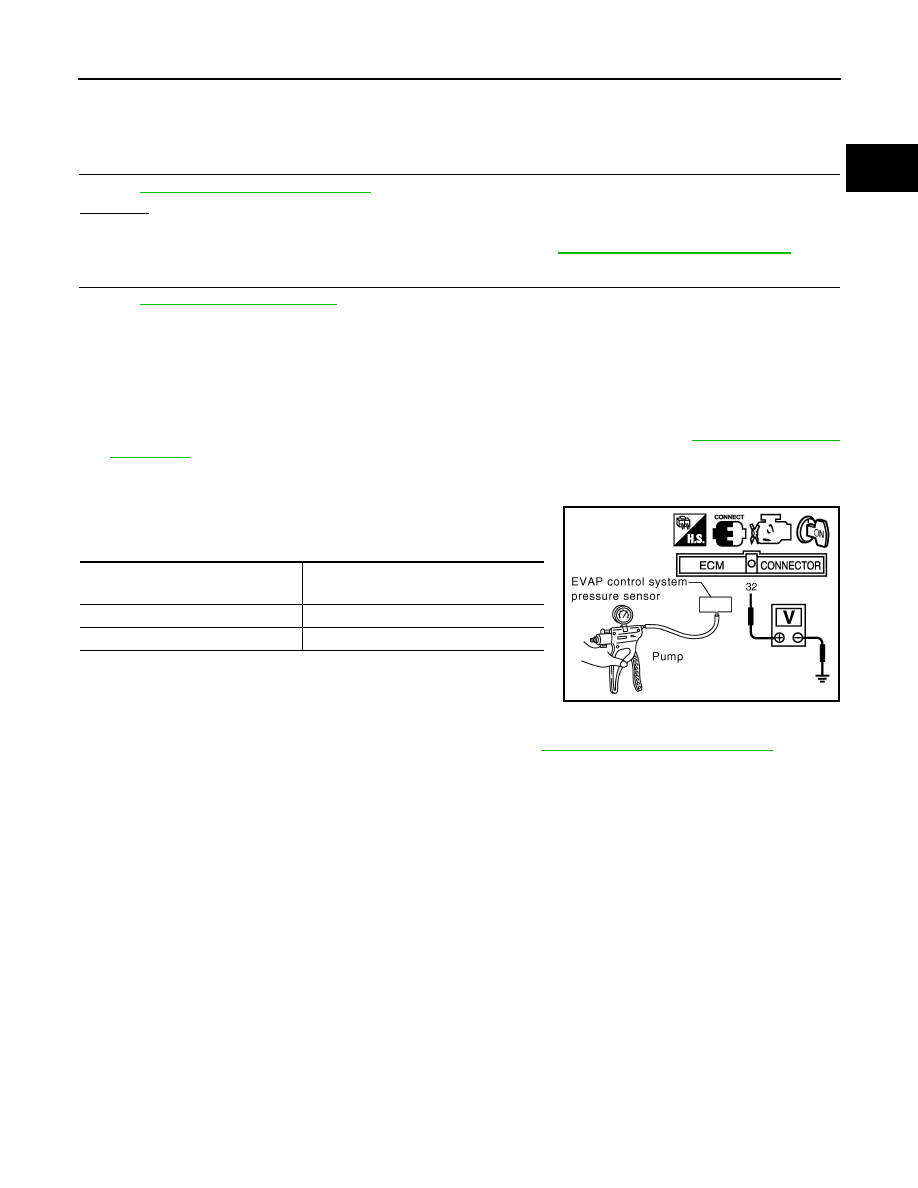
1. Remove EVAP control system pressure sensor with its harness connector. Refer to
.
Always replace O-ring with a new one.
2. Install a vacuum pump to EVAP control system pressure sensor.
3. Turn ignition switch ON and check output voltage between ECM
terminal 32 and ground under the following conditions.
CAUTION:
• Always calibrate the vacuum pump gauge when using it.
• Never apply below -93.3 kPa (-0.952 kg/cm
2
, -13.53 psi) or
pressure over 101.3 kPa (1.033 kg/cm
2
, 14.69 psi).
4. If NG, replace EVAP control system pressure sensor. Refer to
FL-16, "Removal and Installation"
.
Applied vacuum
[kPa (kg/cm
2
, psi)]
Voltage
Not applied
1.8 - 4.8 V
-26.7 (-0.272, -3.87)
2.1 to 2.5 V lower than above value
PBIB1173E
August 2012
2012 Pathfinder