Nissan Pathfinder (2012 year). Manual - part 303
ENGINE CONTROL SYSTEM
EC-505
< SYSTEM DESCRIPTION >
[VK56DE]
C
D
E
F
G
H
I
J
K
L
M
A
EC
N
P
O
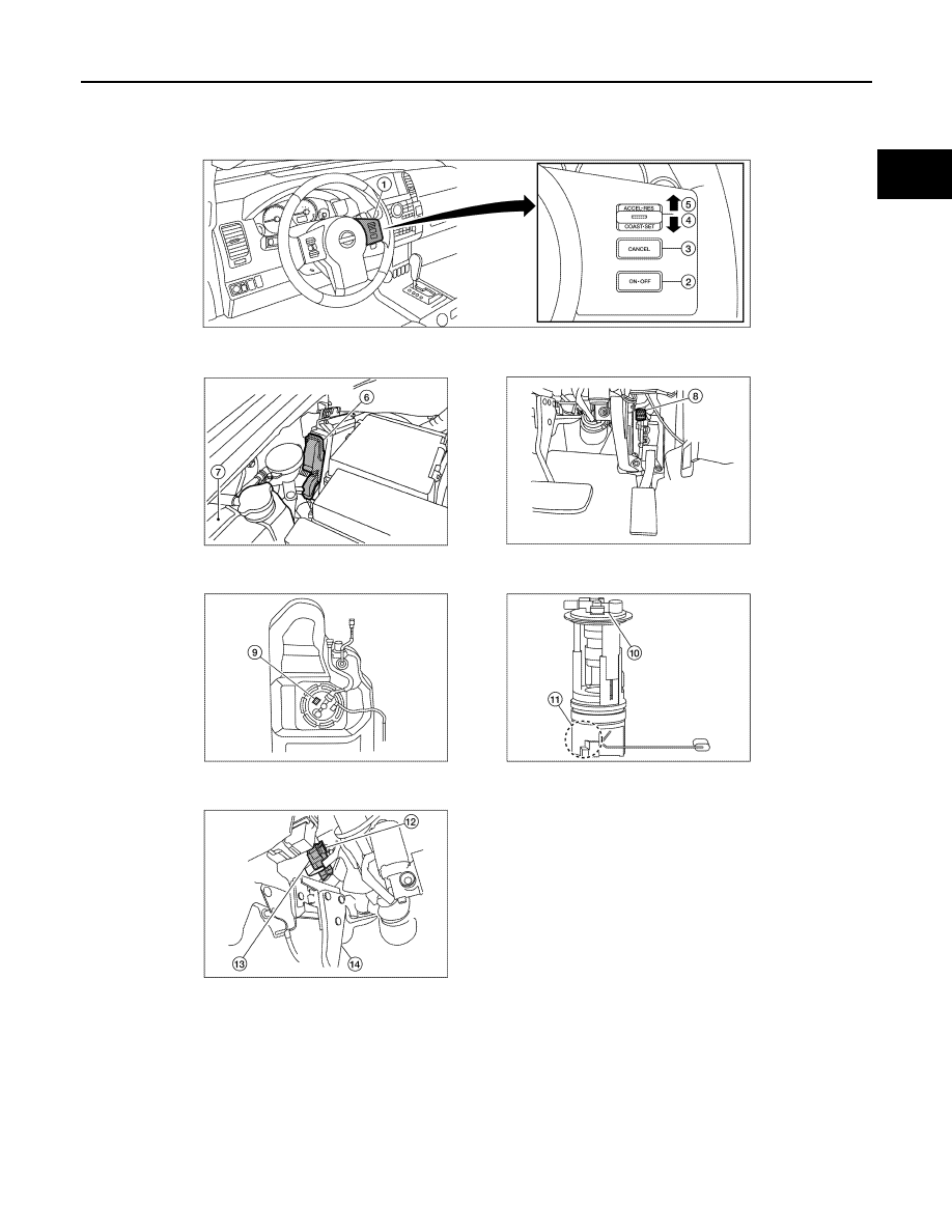
1.
ASCD steering switch
2.
MAIN switch
3.
CANCEL switch
4.
SET/COAST switch
5.
RESUME/ACCELERATE switch
6.
ECM harness connectors (view with
ECM cover removed)
7.
Coolant reservoir
8.
Accelerator pedal position sensor
9.
Fuel level sensor unit and fuel pump
harness connector (view with fuel
tank removed)
AWBIA0084ZZ
August 2012
2012 Pathfinder