Nissan Pathfinder (2012 year). Manual - part 294


  Index      Manuals     Nissan Pathfinder (2012 year) - Service and Repair Manual


Search            copyright infringement  


Content      ..     292      293      294      295     ..


Nissan Pathfinder (2012 year). Manual - part 294


ECM

EC-433

< ECU DIAGNOSIS INFORMATION >

[VQ40DE]

C

D

E

F

G

H

I

J

K

L

M

A

EC

N

P

O

*1: Accelerator pedal position sensor 2 signal and throttle position sensor 2 signal are converted by ECM internally. Thus, they differ
from ECM terminals voltage signal.
*2: Before measuring the terminal voltage, confirm that the battery is fully charged. Refer to 

PG-5, "How to Handle Battery"

.

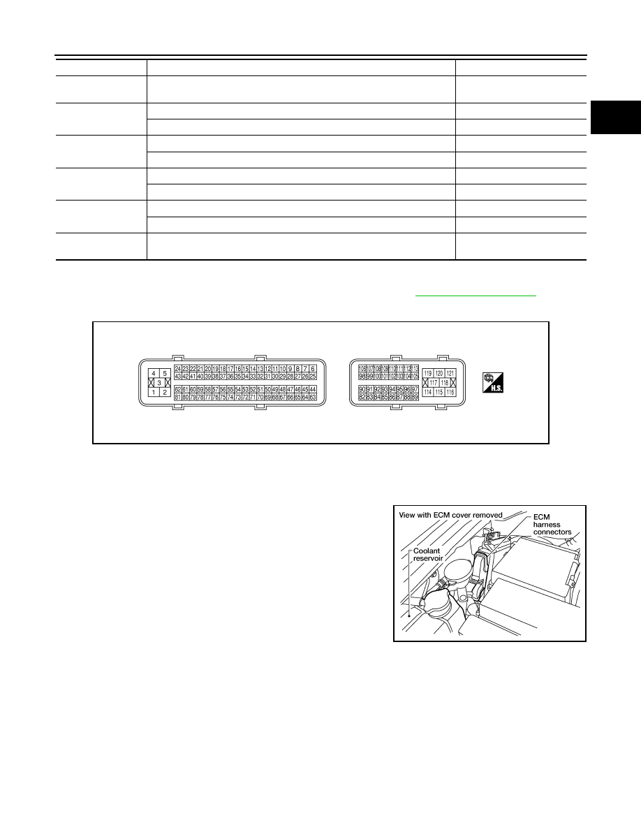
ECM Harness Connector Terminal Layout

INFOID:0000000007358388

ECM Terminal and Reference Value

INFOID:0000000007358389

PREPARATION

ECM located in the engine room passenger side behind reservoir

tank.

ECM INSPECTION TABLE

Specification data are reference values and are measured between each terminal and ground.

Pulse signal is measured by CONSULT.

CAUTION:

Never use ECM ground terminals when measuring input/output voltage. Doing so may result in dam-

age to the ECMs transistor. Use a ground other than ECM terminals, such as the ground.

EVAP DIAG READY

• Ignition switch: ON

Indicates the ready condition of 
EVAP leak diagnosis.

HO2 S2 DIAG1 (B1)

DTC P0139 self-diagnosis (delayed response) is incomplete.

INCMP

DTC P0139 self-diagnosis (delayed response) is complete.

CMPLT

HO2 S2 DIAG1 (B2)

DTC P0159 self-diagnosis (delayed response) is incomplete.

INCMP

DTC P0159 self-diagnosis (delayed response) is complete.

CMPLT

HO2 S2 DIAG2 (B1)

DTC P0139 self-diagnosis (slow response) is incomplete.

INCMP

DTC P0139 self-diagnosis (slow response) is complete.

CMPLT

HO2 S2 DIAG2 (B2)

DTC P0159 self-diagnosis (slow response) is incomplete.

INCMP

DTC P0159 self-diagnosis (slow response) is complete.

CMPLT

THRTL STK CNT B1

NOTE:

The item is indicated, but not used.

MONITOR ITEM

CONDITION

SPECIFICATION

MBIB0045E

BBIA0537E

August 2012

2012 Pathfinder

EC-434

< ECU DIAGNOSIS INFORMATION >

[VQ40DE]

ECM

TER-

MI-

NAL 

NO.

WIRE 

COLOR

ITEM

CONDITION

DATA (DC Voltage)

1

BR

ECM ground

[Engine is running]

• Idle speed

Body ground

2

G

A/F sensor 1 heater (Bank 1)

[Engine is running]

Warm-up condition

• Idle speed

(More than 140 seconds after starting en-
gine)

Approximately 2.9 - 8.8V

3

V

Throttle control motor relay 
power supply

[Ignition switch: ON]

BATTERY VOLTAGE
(11 - 14V)

4

L/W

Throttle control motor (Close)

[Ignition switch: ON]

• Engine: Stopped
• Shift  lever:  D
• Accelerator pedal: Fully released

0 - 14V

5

L/B

Throttle control motor (Open)

[Ignition switch: ON]

• Engine: Stopped
• Shift  lever:  D
• Accelerator pedal: Fully depressed

0 - 14V

6

R

Heated oxygen sensor 2 
heater (Bank 2)

[Engine is running]

• Engine speed is below 3,600 rpm after the 

following conditions are met

- Engine: After warming up
- Keeping the engine speed between 3,500 

and 4,000 rpm for 1 minute and at idle for 1 
minute under no load

0 - 1.0V

[Ignition switch: ON]

• Engine: Stopped

[Engine is running]

• Engine speed: Above 3,600 rpm

BATTERY VOLTAGE
(11 - 14V)

10

W

Intake valve timing control so-
lenoid valve (Bank 2)

[Engine is running]

Warm-up condition

• Idle speed

BATTERY VOLTAGE
(11 - 14V)

[Engine is running]

Warm-up condition

• Engine speed: 2,500 rpm

7 - 12V

PBIA8148J

PBIB1104E

PBIB1105E

PBIB1790E

August 2012

2012 Pathfinder

ECM

EC-435

< ECU DIAGNOSIS INFORMATION >

[VQ40DE]

C

D

E

F

G

H

I

J

K

L

M

A

EC

N

P

O

11

LG

Intake valve timing control so-
lenoid valve (Bank 1)

[Engine is running]

Warm-up condition

• Idle speed

BATTERY VOLTAGE
(11 - 14V)

[Engine is running]

Warm-up condition

• Engine speed: 2,500 rpm

7 - 12V

12

P

Power steering pressure sen-
sor

[Engine is running]

• Steering wheel: Being turned

0.5 - 4.5V

[Engine is running]

• Steering wheel: Not being turned

0.4 - 0.8V

13

G

Crankshaft position sensor 
(POS)

[Engine is running]

Warm-up condition

• Idle speed

NOTE:

The pulse cycle changes depending on rpm 
at idle

Approximately 10V

[Engine is running]

• Engine speed: 2,000 rpm

Approximately 10V

14

Y

Camshaft position sensor 
(PHASE) (Bank 2)

[Engine is running]

Warm-up condition

• Idle speed

NOTE:

The pulse cycle changes depending on rpm 
at idle

1.0 - 4.0V

[Engine is running]

• Engine speed: 2,000 rpm

1.0 - 4.0V

15

W

Knock sensor 
(Bank 1)

[Engine is running]

• Idle speed

Approximately 2.5V

16

BR

A/F sensor 1 (Bank 2)

[Engine is running]

Warm-up condition

• Engine speed: 2,000 rpm

Approximately 1.8V
Output voltage varies with air fuel 
ratio.

TER-

MI-

NAL 

NO.

WIRE 

COLOR

ITEM

CONDITION

DATA (DC Voltage)

PBIB1790E

PBIB1041E

PBIB1042E

PBIB1039E

PBIB1040E

August 2012

2012 Pathfinder

EC-436

< ECU DIAGNOSIS INFORMATION >

[VQ40DE]

ECM

21
22
23

W
LG
SB

Fuel injector No. 5
Fuel injector No. 3
Fuel injector No. 1

[Engine is running]

Warm-up condition

• Idle speed

NOTE:

The pulse cycle changes depending on rpm 
at idle

BATTERY VOLTAGE
(11 - 14V)

[Engine is running]

Warm-up condition

• Engine speed: 2,000 rpm

BATTERY VOLTAGE
(11 - 14V)

24
43

G
G

A/F sensor 1 heater (Bank 2)

[Engine is running]

Warm-up condition

• Idle speed

(More than 140 seconds after starting en-
gine)

Approximately 2.9 - 8.8V

25

P

Heated oxygen sensor 2 
heater (Bank 1)

[Engine is running]

• Engine speed: Below 3,600 rpm after the 

following conditions are met

- Engine: After warming up
- Keeping the engine speed between 3,500 

and 4,000 rpm for 1 minute and at idle for 1 
minute under no load

0 - 1.0V

[Ignition switch: ON]

• Engine: Stopped

[Engine is running]

• Engine speed: Above 3,600 rpm

BATTERY VOLTAGE
(11 - 14V)

29

G

VIAS control solenoid valve

[Engine is running]

• Idle speed

BATTERY VOLTAGE
(11 - 14V)

[Engine is running]

• Engine speed: Between 2,200 and 3,300 

rpm

0 - 1.0V

32

W

EVAP control system pres-
sure sensor

[Ignition switch: ON]

Approximately 1.8 - 4.8V

TER-

MI-

NAL 

NO.

WIRE 

COLOR

ITEM

CONDITION

DATA (DC Voltage)

SEC984C

SEC985C

PBIA8148J

August 2012

2012 Pathfinder

ECM

EC-437

< ECU DIAGNOSIS INFORMATION >

[VQ40DE]

C

D

E

F

G

H

I

J

K

L

M

A

EC

N

P

O

33

L

Camshaft position sensor 
(PHASE) (Bank 1)

[Engine is running]

Warm-up condition

• Idle speed

NOTE:

The pulse cycle changes depending on rpm 
at idle

1.0 - 4.0V

[Engine is running]

• Engine speed: 2,000 rpm

1.0 - 4.0V

34

BR

Intake air temperature sensor

[Engine is running]

Approximately 0 - 4.8V
Output voltage varies with intake 
air temperature.

35

O/L

A/F sensor 1 (Bank 1)

[Engine is running]

Warm-up condition

• Engine speed: 2,000 rpm

Approximately 1.8V
Output voltage varies with air fuel 
ratio.

36

W

Knock sensor
(Bank 2)

[Engine is running]

• Idle speed

Approximately 2.5V

40
41
42

V
R
O

Fuel injector No. 6
Fuel injector No. 4 
Fuel injector No. 2

[Engine is running]

Warm-up condition

• Idle speed

NOTE:

The pulse cycle changes depending on rpm 
at idle

BATTERY VOLTAGE
(11 - 14V)

[Engine is running]

Warm-up condition

• Engine speed: 2,000 rpm

BATTERY VOLTAGE
(11 - 14V)

TER-

MI-

NAL 

NO.

WIRE 

COLOR

ITEM

CONDITION

DATA (DC Voltage)

PBIB1039E

PBIB1040E

SEC984C

SEC985C

August 2012

2012 Pathfinder

EC-438

< ECU DIAGNOSIS INFORMATION >

[VQ40DE]

ECM

45

R

EVAP canister purge volume 
control solenoid valve

[Engine is running]

• Idle speed
• Accelerator pedal is not depressed even 

slightly, after engine starting

BATTERY VOLTAGE
(11 - 14V)

[Engine is running]

• Engine speed: About 2,000 rpm (More than 

100 seconds after starting engine)

BATTERY VOLTAGE
(11 - 14V)

47

L

Sensor power supply (Throt-
tle position sensor)

[Ignition switch: ON]

Approximately 5V

48

SB

Sensor power supply
(EVAP control system pres-
sure sensor)

[Ignition switch: ON]

Approximately 5V

49

P

Sensor power supply
(Refrigerant pressure sensor/
Battery current sensor)

[Ignition switch: ON]

Approximately 5V

50

W

Throttle position sensor 1

[Ignition switch: ON]

• Engine: Stopped
• Shift  lever:  D
• Accelerator pedal: Fully released

More than 0.36V

[Ignition switch: ON]

• Engine: Stopped
• Shift  lever:  D
• Accelerator pedal: Fully depressed

Less than 4.75V

51

P

Mass air flow sensor

[Engine is running]

Warm-up condition

• Idle speed

0.9 - 1.2V

[Engine is running]

Warm-up condition

• Engine speed: 2,500 rpm

1.5 - 1.8V

55

G

Heated oxygen sensor 2 
(Bank 2)

[Engine is running]

• Revving engine from idle to 3,000 rpm 

quickly after the following conditions are 
met

- Engine: After warming up
- Keeping the engine speed between 3,500 

and 4,000 rpm for 1 minute and at idle for 1 
minute under no load

0 - Approximately 1.0V

56

W/L

A/F sensor 1 (Bank 1)

[Ignition switch: ON]

Approximately 2.2V

TER-

MI-

NAL 

NO.

WIRE 

COLOR

ITEM

CONDITION

DATA (DC Voltage)

SEC990C

SEC991C

August 2012

2012 Pathfinder

ECM

EC-439

< ECU DIAGNOSIS INFORMATION >

[VQ40DE]

C

D

E

F

G

H

I

J

K

L

M

A

EC

N

P

O

60
61
62

SB
L
Y

Ignition signal No. 5
Ignition signal No. 3
Ignition signal No. 1

[Engine is running]

Warm-up condition

• Idle speed

NOTE:

The pulse cycle changes depending on rpm 
at idle

0 - 0.2V

[Engine is running]

Warm-up condition

• Engine speed: 2,500 rpm

0.1 - 0.4V

66

B

Sensor ground
(Throttle position sensor)

[Engine is running]

Warm-up condition

• Idle speed

Approximately 0V

67

B

Sensor ground

[Engine is running]

Warm-up condition

• Idle speed

Approximately 0V

68

G

Sensor power supply
(Power steering pressure 
sensor)

[Ignition switch: ON]

Approximately 5V

69

R

Throttle position sensor 2

[Ignition switch: ON]

• Engine: Stopped
• Shift  lever:  D
• Accelerator pedal: Fully released

Less than 4.75V

[Ignition switch: ON]

• Engine: Stopped
• Shift  lever:  D
• Accelerator pedal: Fully depressed

More than 0.36V

70

BR

Refrigerant pressure sensor

[Engine is running]

Warm-up condition

• Both A/C switch and blower switch: ON 

(Compressor operates)

1.0 - 4.0V

71

R

Battery current sensor

[Engine is running]

• Battery: Fully charged*
• Idle speed

Approximately 2.6 - 3.5V

73

Y

Engine coolant temperature 
sensor

[Engine is running]

Approximately 0 - 4.8V
Output voltage varies with engine 
coolant temperature.

74

W

Heated oxygen sensor 2 
(Bank 1)

[Engine is running]

• Revving engine from idle to 3,000 rpm 

quickly after the following conditions are 
met

- Engine: After warming up
- Keeping the engine speed between 3,500 

and 4,000 rpm for 1 minute and at idle for 1 
minute under no load

0 - Approximately 1.0V

75

B/R

A/F sensor 1 (Bank 2)

[Ignition switch: ON]

Approximately 2.2V

78

GR

Sensor ground
(Heated oxygen sensor 2)

[Engine is running]

Warm-up condition

• Idle speed

Approximately 0V

TER-

MI-

NAL 

NO.

WIRE 

COLOR

ITEM

CONDITION

DATA (DC Voltage)

SEC986C

SEC987C

August 2012

2012 Pathfinder

EC-440

< ECU DIAGNOSIS INFORMATION >

[VQ40DE]

ECM

79
80
81

P
GR
G

Ignition signal No. 6
Ignition signal No. 4
Ignition signal No. 2

[Engine is running]

Warm-up condition

• Idle speed

NOTE:

The pulse cycle changes depending on rpm 
at idle

0 - 0.2V

[Engine is running]

Warm-up condition

• Engine speed: 2,500 rpm

0.1 - 0.4V

82

B

Sensor ground
(APP sensor 1)

[Engine is running]

Warm-up condition

• Idle speed

Approximately 0V

83

B

Sensor ground
(APP sensor 2)

[Engine is running]

Warm-up condition

• Idle speed

Approximately 0V

85

W

Data link connector

[Ignition switch: ON]

• CONSULT or GST: disconnected

Approximately 5V - Battery volt-
age (11 - 14V)

86

P

CAN communication line

90

L

Sensor power supply
(APP sensor 1)

[Ignition switch: ON]

Approximately 5V

91

G

Sensor power supply
(APP sensor 2)

[Ignition switch: ON]

Approximately 5V

94

L

CAN communication line

98

GR

Accelerator pedal position 
sensor 2

[Ignition switch: ON]

• Engine: Stopped
• Accelerator pedal: Fully released

0.28 - 0.48V

[Ignition switch: ON]

• Engine: Stopped
• Accelerator pedal: Fully depressed

More than 2.0

99

SB

ASCD steering switch

[Ignition switch: ON]

• ASCD steering switch: OFF

Approximately 4V

[Ignition switch: ON]

• MAIN switch: Pressed

Approximately 0V

[Ignition switch: ON]

• CANCEL switch: Pressed

Approximately 1V

[Ignition switch: ON]

• RESUME/ACCELERATE switch: Pressed

Approximately 3V

[Ignition switch: ON]

• SET/COAST switch: Pressed

Approximately 2V

101

LG

Stop lamp switch

[Ignition switch: OFF]

• Brake pedal: Fully released

Approximately 0V

[Ignition switch: OFF]

• Brake pedal: Slightly depressed

BATTERY VOLTAGE
(11 - 14V)

TER-

MI-

NAL 

NO.

WIRE 

COLOR

ITEM

CONDITION

DATA (DC Voltage)

SEC986C

SEC987C

August 2012

2012 Pathfinder


Content      ..     292      293      294      295     ..