Nissan Pathfinder (2012 year). Manual - part 292
ON BOARD REFUELING VAPOR RECOVERY (ORVR)
EC-417
< DTC/CIRCUIT DIAGNOSIS >
[VQ40DE]
C
D
E
F
G
H
I
J
K
L
M
A
EC
N
P
O
2.
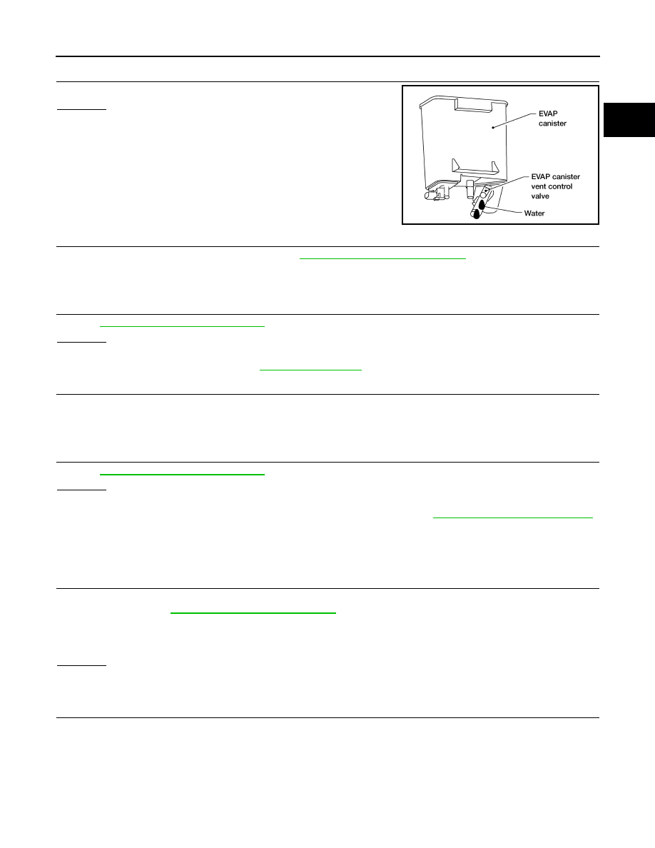
CHECK IF EVAP CANISTER IS SATURATED WITH WATER
Does water drain from the EVAP canister?
Yes or No
Yes
>> GO TO 3.
No
>> GO TO 6.
3.
REPLACE EVAP CANISTER
Replace EVAP canister with a new one. Refer to
FL-16, "Removal and Installation"
>> GO TO 4.
4.
CHECK DRAIN FILTER
EC-419, "Component Inspection"
OK or NG
OK
>> GO TO 5.
NG
>> Replace drain filter. Refer to
.
5.
DETECT MALFUNCTIONING PART
Check the EVAP hose between EVAP canister and vehicle frame for clogging or poor connection.
>> Repair or replace EVAP hose.
6.
CHECK REFUELING EVAP VAPOR CUT VALVE
EC-419, "Component Inspection"
OK or NG
OK
>>
INSPECTION END
NG
>> Replace refueling EVAP vapor cut valve with fuel tank. Refer to
FL-6, "Removal and Installation"
SYMPTOM: CANNOT REFUEL/FUEL ODOR FROM THE FUEL FILLER OPENING IS STRONG
WHILE REFUELING.
1.
CHECK EVAP CANISTER
1. Remove EVAP canister with EVAP canister vent control valve and EVAP control system pressure sensor
attached. Refer to
FL-16, "Removal and Installation"
.
2. Weigh the EVAP canister with EVAP canister vent control valve and EVAP control system pressure sensor
attached.
The weight should be less than 2.0 kg (4.4 lb).
OK or NG
OK
>> GO TO 2.
NG
>> GO TO 3.
2.
CHECK IF EVAP CANISTER IS SATURATED WITH WATER
BBIA0558E
August 2012
2012 Pathfinder