Nissan Pathfinder (2012 year). Manual - part 288
P2138 APP SENSOR
EC-385
< DTC/CIRCUIT DIAGNOSIS >
[VQ40DE]
C
D
E
F
G
H
I
J
K
L
M
A
EC
N
P
O
Diagnosis Procedure
INFOID:0000000007358353
1.
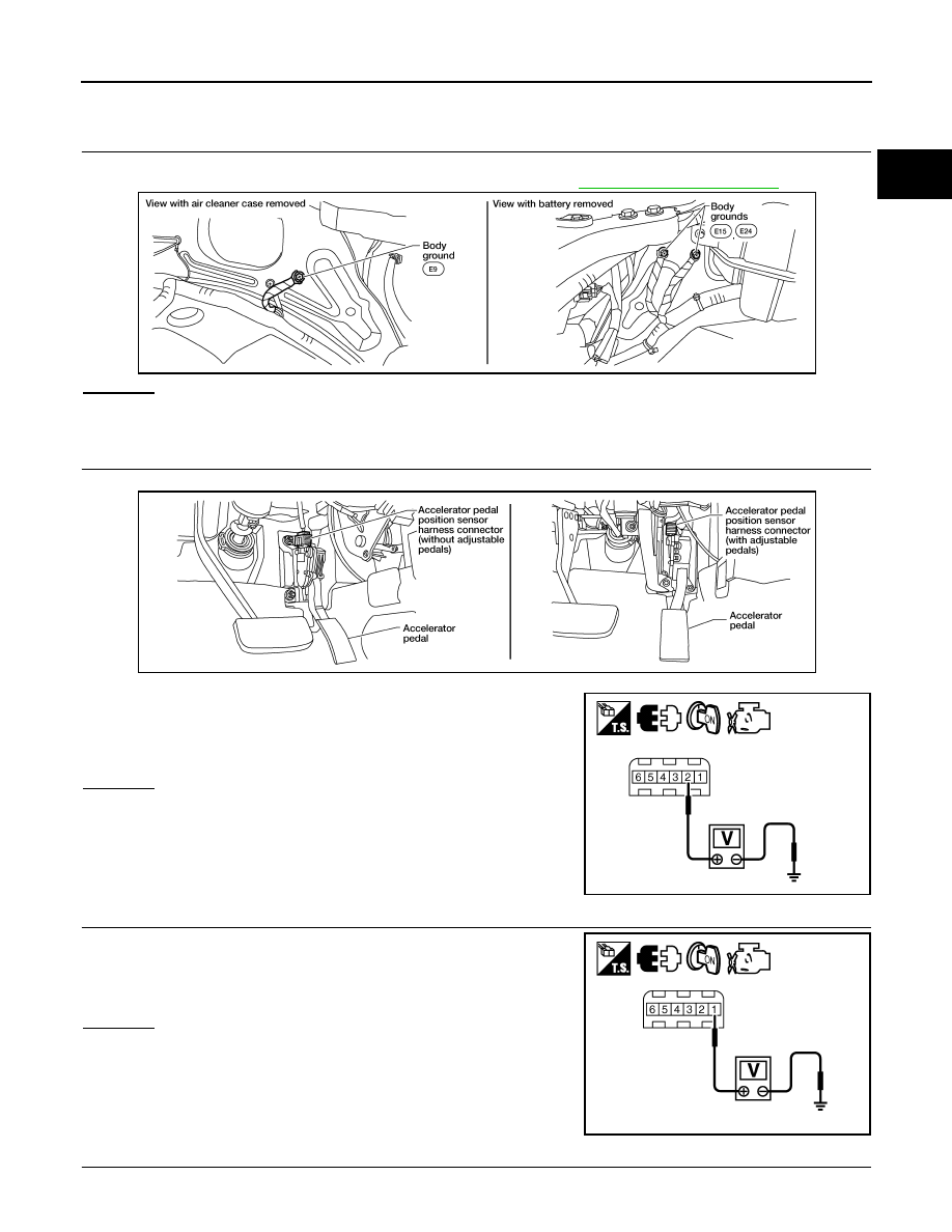
CHECK GROUND CONNECTIONS
1. Turn ignition switch OFF.
2. Loosen and retighten three ground screws on the body. Refer to
OK or NG
OK
>> GO TO 2.
NG
>> Repair or replace ground connections.
2.
CHECK APP SENSOR 1 POWER SUPPLY CIRCUIT
1. Disconnect accelerator pedal position (APP) sensor harness connector.
2. Turn ignition switch ON.
3. Check voltage between APP sensor terminals 2 and ground with
CONSULT or tester.
OK or NG
OK
>> GO TO 3.
NG
>> Repair open circuit or short to ground or short to power
in harness or connectors.
3.
CHECK APP SENSOR 2 POWER SUPPLY CIRCUIT-I
Check voltage between APP sensor terminal 1 and ground with
CONSULT or tester.
1.
OK or NG
OK
>> GO TO 8.
NG
>> GO TO 4.
4.
CHECK APP SENSOR 2 POWER SUPPLY CIRCUIT-II
1. Turn ignition switch OFF.
BBIA0539E
Voltage: Approximately 5V
BBIA0556E
PBIB2608E
Voltage: Approximately 5V
PBIB2611E
August 2012
2012 Pathfinder