Nissan Pathfinder (2012 year). Manual - part 265
P0181 FTT SENSOR
EC-201
< DTC/CIRCUIT DIAGNOSIS >
[VQ40DE]
C
D
E
F
G
H
I
J
K
L
M
A
EC
N
P
O
>>
INSPECTION END
Component Inspection
INFOID:0000000007358112
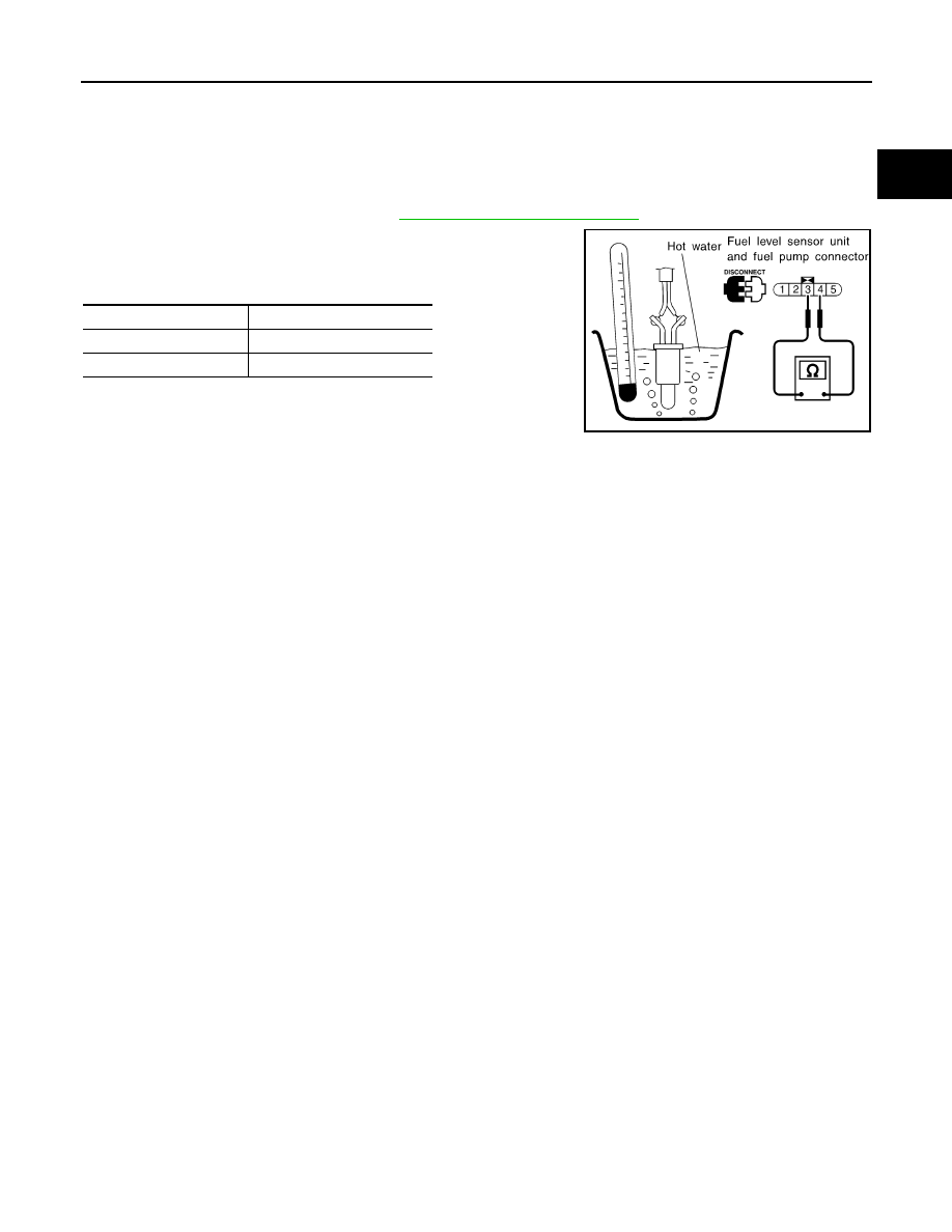
FUEL TANK TEMPERATURE SENSOR
1. Remove fuel level sensor unit. Refer to
FL-11, "Removal and Installation"
.
2. Check resistance between “fuel level sensor unit and fuel pump”
terminals 3 and 4 by heating with hot water or heat gun as
shown in the figure.
Temperature
°
C (
°
F)
Resistance k
Ω
20 (68)
2.3 - 2.7
50 (122)
0.79 - 0.90
SEF476YA
August 2012
2012 Pathfinder