Nissan Pathfinder (2012 year). Manual - part 263
P0171, P0174 FUEL INJECTION SYSTEM FUNCTION
EC-185
< DTC/CIRCUIT DIAGNOSIS >
[VQ40DE]
C
D
E
F
G
H
I
J
K
L
M
A
EC
N
P
O
P0171, P0174 FUEL INJECTION SYSTEM FUNCTION
On Board Diagnosis Logic
INFOID:0000000007358101
With the Air-Fuel Mixture Ratio Self-Learning Control, the actual mixture ratio can be brought closely to the
theoretical mixture ratio based on the mixture ratio feedback signal from the air fuel ratio (A/F) sensor 1. The
ECM calculates the necessary compensation to correct the offset between the actual and the theoretical
ratios.
In case the amount of the compensation value is extremely large (the actual mixture ratio is too lean), the
ECM judges the condition as the fuel injection system malfunction and illuminates the MIL (2 trip detection
logic).
DTC Confirmation Procedure
INFOID:0000000007358102
NOTE:
If DTC Confirmation Procedure has been previously conducted, always turn ignition switch OFF and wait at
least 10 seconds before conducting the next test.
WITH CONSULT
1. Start engine and warm it up to normal operating temperature.
2. Turn ignition switch OFF and wait at least 10 seconds.
3. Turn ignition switch ON and select “SELF-LEARNING CONT” in “WORK SUPPORT” mode with CON-
SULT.
4. Clear the self-learning control coefficient by touching “CLEAR”.
5. Start engine.
If it is difficult to start engine, the fuel injection system has a malfunction.
Performing the following procedure is advised.
a. Crank engine while depressing accelerator pedal.
NOTE:
When depressing accelerator pedal three-fourths (3/4) or more, the control system does not start the
engine. Do not depress accelerator pedal too much.
b. If engine starts, go to
.
If engine does not start, check exhaust and intake air leakage visually.
6. Keep engine at idle for at least 5 minutes.
7. Check 1st trip DTC.
8. The 1st trip DTC P0171 or P0174 should be detected at this stage, if a malfunction exists. If so, go to
NOTE:
If 1st trip DTC is not detected during above procedure, performing the following procedure is advised.
a. Turn ignition switch OFF and wait at least 10 seconds.
b. Start engine.
c. Maintain the following conditions for at least 10 consecutive minutes.
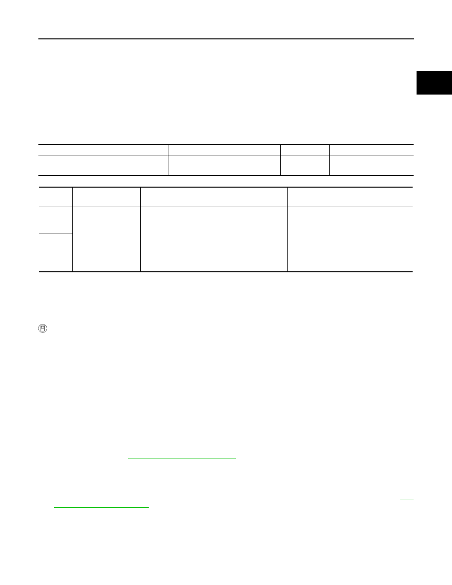
Sensor
Input signal to ECM
ECM function
Actuator
A/F sensor 1
Density of oxygen in exhaust gas
(Mixture ratio feedback signal)
Fuel injection
control
Fuel injector
DTC No.
Trouble diagnosis
name
DTC detecting condition
Possible cause
P0171
0171
(Bank 1)
Fuel injection system
too lean
• Fuel injection system does not operate properly.
• The amount of mixture ratio compensation is too
large. (The mixture ratio is too lean.)
• Intake air leaks
• Air fuel ratio (A/F) sensor 1
• Fuel injector
• Exhaust gas leaks
• Incorrect fuel pressure
• Lack of fuel
• Mass air flow sensor
• Incorrect PCV hose connection
P0174
0174
(Bank 2)
August 2012
2012 Pathfinder