Nissan Pathfinder (2012 year). Manual - part 256
P0116 ECT SENSOR
EC-129
< DTC/CIRCUIT DIAGNOSIS >
[VQ40DE]
C
D
E
F
G
H
I
J
K
L
M
A
EC
N
P
O
P0116 ECT SENSOR
Component Description
INFOID:0000000007358036
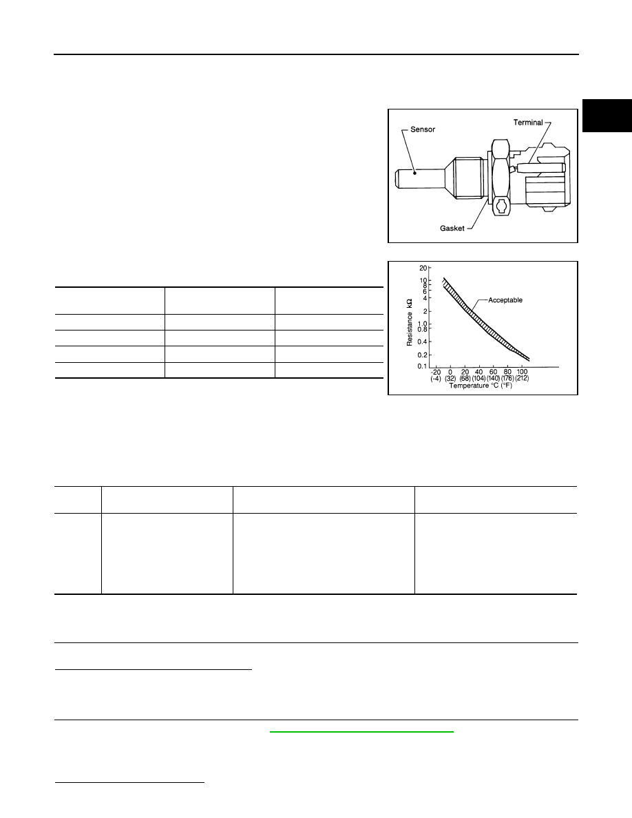
The engine coolant temperature sensor is used to detect the engine
coolant temperature. The sensor modifies a voltage signal from the
ECM. The modified signal returns to the ECM as the engine coolant
temperature input. The sensor uses a thermistor which is sensitive to
the change in temperature. The electrical resistance of the ther-
mistor decreases as temperature increases.
<Reference data>
*: This data is reference value and is measured between ECM terminal 73 (Engine
coolant temperature sensor) and 67 (Sensor ground).
CAUTION:
Never use ECM ground terminals when measuring input/output voltage. Doing so may result in dam-
age to the ECM's transistor. Use a ground other than ECM terminals, such as the ground.
On Board Diagnosis Logic
INFOID:0000000007358037
DTC Confirmation Procedure
INFOID:0000000007358038
1.
INSPECTION START
Is it necessary to erase permanent DTC?
YES
>> GO TO 3.
NO
>> GO TO 2.
2.
PERFORM COMPONENT FUNCTION CHECK
Perform component function check. Refer to
EC-130, "Component Function Check"
.
NOTE:
Use the component function check to check the overall function of the ECT sensor circut. During this check, a
1st trip DTC might not be confirmed.
Is the inspection result normal?
SEF594K
Engine coolant
temperature
°
C (
°
F)]
Voltage* (V)
Resistance (k
Ω
)
−
10 (14)
4.4
7.0 - 11.4
20 (68)
3.5
2.1 - 2.9
50 (122)
2.2
0.68 - 1.00
90 (194)
0.9
0.236 - 0.260
SEF012P
DTC No.
Trouble diagnosis
(Trouble diagnosis content)
DTC detecting condition
Possible cause
P0116
ECT SEN/CIRC
[Engine coolant temperature
(ECT) sensor circuit range/per-
formance]
The comparison result of signals transmitted
to ECM from each temperature sensor (IAT
sensor, ECT sensor, and FTT sensor) shows
that the voltage signal of the ECT sensor is
higher/lower than that of other temperature
sensors when the engine is started with its
cold state.
• Harness or connectors
(High or low resistance in the ECT
sensor circuit)
• ECT sensor
August 2012
2012 Pathfinder