Nissan Pathfinder (2012 year). Manual - part 235


  Index      Manuals     Nissan Pathfinder (2012 year) - Service and Repair Manual


Search            copyright infringement  


Content      ..     233      234      235      236     ..


Nissan Pathfinder (2012 year). Manual - part 235


REAR FINAL DRIVE

DLN-445

< UNIT DISASSEMBLY AND ASSEMBLY >

[REAR FINAL DRIVE: R200]

C

E

F

G

H

I

J

K

L

M

A

B

DLN

N

O

P

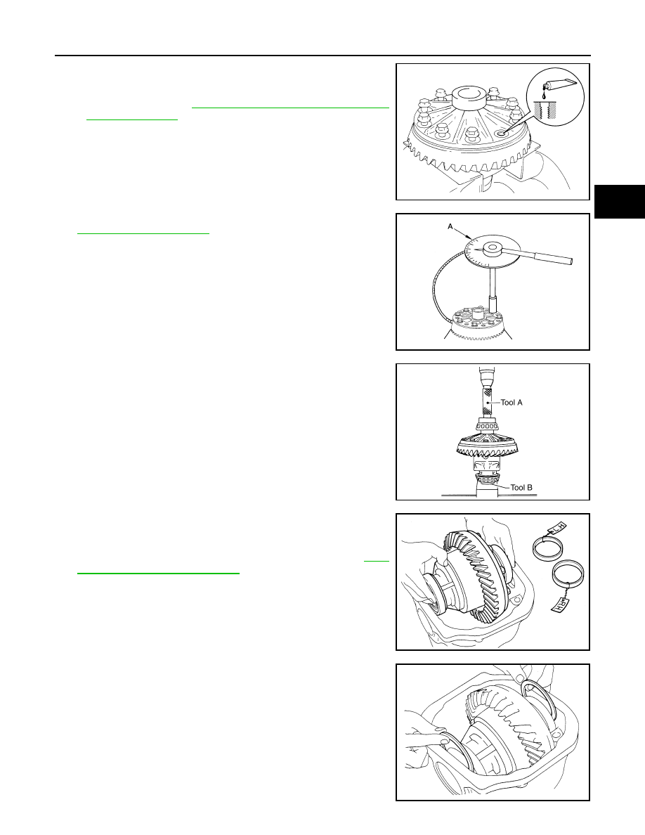
8. Apply thread locking sealant into the threaded holes of the drive

gear and install the bolts.

• Use Genuine Medium Strength Thread Locking Sealant or

equivalent. Refer to 

GI-14, "Recommended Chemical Prod-

ucts and Sealants"

.

CAUTION:

Make sure the drive gear back and threaded holes are

clean.

9. Tighten the drive gear bolts to the specified torque. Refer to

DLN-429, "Exploded View"

After tightening the drive gear bolts

to the specified torque, tighten an additional 31

°

 to 36

°

 using

Tool (A).

CAUTION:

• Always use Tool. Avoid tightening based on visual check

alone.

• Tighten drive gear bolts in a crisscross pattern.

10. Press the side bearing inner races into the differential case

using Tools.

CAUTION:

Do not reuse side bearing inner race.

11. Install the differential case assembly with the side bearing outer

races into the gear carrier.

12. Measure the side bearing preload torque. If necessary, select

the appropriate side bearing adjusting washers. Refer to 

DLN-

447, "Inspection and Adjustment"

.

13. Insert the selected left and right side bearing adjusting washers

in place between the side bearings and gear carrier.

SDIA2594E

Tool number

(A): KV10112100 (BT-8653-A)

AWBIA0722ZZ

Tool number

(A): KV38100300 (J-25523)
(B): ST33061000 (J-8107-2)

SPD353

SPD919

SPD924

August 2012

2012 Pathfinder

DLN-446

< UNIT DISASSEMBLY AND ASSEMBLY >

[REAR FINAL DRIVE: R200]

REAR FINAL DRIVE

14. Install the side bearing caps with the matching marks aligned

and tighten the side bearing cap bolts to the specified torque.

Refer to 

DLN-429, "Exploded View"

.

15. Check and adjust the drive gear runout, tooth contact, drive gear to drive pinion backlash, and total pre-

load torque. Refer to 

DLN-447, "Inspection and Adjustment"

Recheck the above items.

16. Install the side flanges. Refer to 

DLN-429, "Exploded View"

.

17. Apply a 3.2 mm (0.126 in) bead of sealant to the mating surface

of the carrier cover.

• Use Genuine Silicone RTV or equivalent. Refer to 

GI-14,

"Recommended Chemical Products and Sealants"

.

CAUTION:

Remove any old sealant adhering to the mating surfaces.

Also remove any moisture, oil, or foreign material adhering

to the application and mating surfaces.

18. Install the carrier cover to the gear carrier. Tighten the bolts to

the specified torque. Refer to 

DLN-429, "Exploded View"

.

19. Install the side flange. Refer to 

DLN-429, "Exploded View"

.

Side Flange

1. Apply multi-purpose grease to the lips and differential gear oil to

the circumference of the new side oil seal. Then drive the new

side oil seal in evenly until it becomes flush with the gear carrier

using Tool.

CAUTION:

• Do not reuse side oil seal.

• Do not incline the new side oil seal when installing.

• Apply multi-purpose grease to the lips and differential

gear oil to the circumference of the new side oil seal.

2. Install the side flange using Tool.
a. Install the Tool to the side oil seal as shown.

b. Insert the side flange until the serrated part of the side flange

has engaged the serrated part of the side gear and remove the

Tool.

c.

Drive in the side flange using suitable tool.

NOTE:

Installation is completed when the driving sound of the side

flange turns into a sound which seems to affect the whole rear

final drive assembly.

SPD889

WDIA0282E

Tool number

: KV38100200 (J-26233)

SPD560

Tool number

: KV38107900 (J-39352)

SDIA0822E

August 2012

2012 Pathfinder

SERVICE DATA AND SPECIFICATIONS (SDS)

DLN-447

< SERVICE DATA AND SPECIFICATIONS (SDS) 

[REAR FINAL DRIVE: R200]

C

E

F

G

H

I

J

K

L

M

A

B

DLN

N

O

P

SERVICE DATA AND SPECIFICATIONS (SDS)

SERVICE DATA AND SPECIFICATIONS (SDS)

General Specification

INFOID:0000000007357652

Inspection and Adjustment

INFOID:0000000007357653

DRIVE GEAR RUNOUT

Unit: mm (in)

SIDE GEAR CLEARANCE

Unit: mm (in)

PRELOAD TORQUE

BACKLASH

Unit: mm (in)

COMPANION FLANGE RUNOUT

Unit: mm (in)

SELECTIVE PARTS

Side Gear Thrust Washer

Applied model

VQ40DE

2WD

4WD

Final drive model

R200

Gear ratio

3.133

3.357

Number of teeth (Drive gear/Drive pinion)

47/15

47/14

Oil capacity (Approx.)

1.4 

 (3 US pt, 2-1/2 lmp pt)

Number of pinion gears

2

Drive pinion adjustment spacer type

Collapsible

Item

Runout limit

Drive gear back face

 0.05 (0.0020) or less

Item

Specification

Side gear back clearance
(Clearance between side gear and differential case for adjusting 
side gear backlash)

0.2 (0.008) or less

(Each gear should rotate smoothly without excessive resistance 

during differential motion.)

Item

Specification

Drive pinion bearing preload torque

2.65 - 3.23 N·m (0.27 - 0.32 kg

m, 24 - 28 in-lb)

Side bearing preload torque (reference value determined by drive 
gear bolt pulling force)

0.20 - 0.52 N·m (0.02 - 0.05 kg

m, 2 - 4 in-lb)

Drive gear bolt pulling force (by spring gauge)

34.2 

 39.2 N (3.5 

 4 kg, 7.7 

 8.8 lb)

Total preload torque
(Total preload torque = drive pinion bearing preload torque + Side 
bearing preload torque)

2.84 - 3.75 N·m (0.29 - 0.38 kg

m, 26 - 33 in-lb)

Item

Specification

Drive gear to drive pinion gear

0.10 - 0.15 (0.0039 - 0.0059)

Item

Runout limit

Outer side of the companion flange

 0.08 (0.0031) or less

August 2012

2012 Pathfinder

DLN-448

< SERVICE DATA AND SPECIFICATIONS (SDS) 

[REAR FINAL DRIVE: R200]

SERVICE DATA AND SPECIFICATIONS (SDS)

Unit: mm (in)

*: Always check with the Parts Department for the latest parts information.

Drive Pinion Height Adjusting Washer

Unit: mm (in)

*: Always check with the Parts Department for the latest parts information.

Side Bearing Adjusting Washer

Unit: mm (in)

*: Always check with the Parts Department for the latest parts information.

Thickness Part 

number*

Thickness Part 

number*

0.75 (0.0295)
0.78 (0.0307)
0.81 (0.0319)
0.84 (0.0331)

38424 0C000
38424 0C001
38424 0C002
38424 0C003

0.87 (0.0343)
0.90 (0.0350)
0.93 (0.0366)

38424 0C004
38424 0C005
38424 0C006

Thickness 

Part number*

Thickness 

Part number*

3.05 (0.1201)
3.08 (0.1213)

3.11 (0.1224)

3.14 (0.1236)

38154 0C000
38154 0C001
38154 0C002
38154 0C003

3.17 (0.1248)
3.20 (0.1260)
3.23 (0.1272)
3.26 (0.1283)

38154 0C004
38154 0C005
38154 0C006
38154 0C007

Thickness

Part number*

Thickness

Part number*

2.00 (0.0787)
2.05 (0.0807)
2.10 (0.0827)
2.15 (0.0846)
2.20 (0.0866)
2.25 (0.0886)
2.30 (0.0906)

38453 N3100
38453 N3101
38453 N3102
38453 N3103
38453 N3104
38453 N3105
38453 N3106

2.35 (0.0925)
2.40 (0.0945)
2.45 (0.0965)
2.50 (0.0984)
2.55 (0.1004)
2.60 (0.1024)
2.65 (0.1043)

38453 N3107
38453 N3108
38453 N3109

38453 N3110

38453 N3111

38453 N3112
38453 N3113

August 2012

2012 Pathfinder

PRECAUTIONS

DLN-449

< PRECAUTION >

[REAR FINAL DRIVE: R230]

C

E

F

G

H

I

J

K

L

M

A

B

DLN

N

O

P

PRECAUTION

PRECAUTIONS

Precaution for Supplemental Restraint System (SRS) "AIR BAG" and "SEAT BELT 
PRE-TENSIONER"

INFOID:0000000007357654

The Supplemental Restraint System such as “AIR BAG” and “SEAT BELT PRE-TENSIONER”, used along

with a front seat belt, helps to reduce the risk or severity of injury to the driver and front passenger for certain

types of collision. This system includes seat belt switch inputs and dual stage front air bag modules. The SRS

system uses the seat belt switches to determine the front air bag deployment, and may only deploy one front

air bag, depending on the severity of a collision and whether the front occupants are belted or unbelted.

Information necessary to service the system safely is included in the SR and SB section of this Service Man-

ual.

WARNING:

• To avoid rendering the SRS inoperative, which could increase the risk of personal injury or death in

the event of a collision which would result in air bag inflation, all maintenance must be performed by

an authorized NISSAN/INFINITI dealer.

• Improper maintenance, including incorrect removal and installation of the SRS, can lead to personal

injury caused by unintentional activation of the system. For removal of Spiral Cable and Air Bag

Module, see the SR section.

• Do not use electrical test equipment on any circuit related to the SRS unless instructed to in this

Service Manual. SRS wiring harnesses can be identified by yellow and/or orange harnesses or har-

ness connectors.

PRECAUTIONS WHEN USING POWER TOOLS (AIR OR ELECTRIC) AND HAMMERS

WARNING:

• When working near the Airbag Diagnosis Sensor Unit or other Airbag System sensors with the Igni-

tion ON or engine running, DO NOT use air or electric power tools or strike near the sensor(s) with a

hammer. Heavy vibration could activate the sensor(s) and deploy the air bag(s), possibly causing

serious injury.

• When using air or electric power tools or hammers, always switch the Ignition OFF, disconnect the

battery, and wait at least 3 minutes before performing any service.

Precaution Necessary for Steering Wheel Rotation After Battery Disconnect

INFOID:0000000007357655

NOTE:

• This Procedure is applied only to models with Intelligent Key system and NATS (NISSAN ANTI-THEFT SYS-

TEM).

• Remove and install all control units after disconnecting both battery cables with the ignition knob in the

LOCK

 position.

• Always use CONSULT to perform self-diagnosis as a part of each function inspection after finishing work. If

DTC is detected, perform trouble diagnosis according to self-diagnostic results.

For models equipped with the Intelligent Key system and NATS, an electrically controlled steering lock mech-

anism is adopted on the key cylinder.

For this reason, if the battery is disconnected or if the battery is discharged, the steering wheel will lock and

steering wheel rotation will become impossible.

If steering wheel rotation is required when battery power is interrupted, follow the procedure below before

starting the repair operation.

OPERATION PROCEDURE

1. Connect both battery cables.

NOTE:

Supply power using jumper cables if battery is discharged.

2. Use the Intelligent Key or mechanical key to turn the ignition switch to the 

ACC

 position. At this time, the

steering lock will be released.

3. Disconnect both battery cables. The steering lock will remain released and the steering wheel can be

rotated.

4. Perform the necessary repair operation.

August 2012

2012 Pathfinder

DLN-450

< PRECAUTION >

[REAR FINAL DRIVE: R230]

PRECAUTIONS

5. When the repair work is completed, return the ignition switch to the 

LOCK

 position before connecting

the battery cables. (At this time, the steering lock mechanism will engage.)

6. Perform a self-diagnosis check of all control units using CONSULT. 

Precaution for Servicing Rear Final Drive

INFOID:0000000007357656

• Before starting diagnosis of the vehicle, understand the symptoms well. Perform correct and systematic

operations. 

• Check for the correct installation status prior to removal or disassembly. When matching marks are required,

be certain they do not interfere with the function of the parts they are applied to. 

• Overhaul should be done in a clean work area, a dust proof area is recommended.

• Before disassembly, completely remove sand and mud from the exterior of the unit, preventing them from

entering into the unit during disassembly or assembly.

• Always use shop paper for cleaning the inside of components.

• Avoid using cotton gloves or a shop cloth to prevent the entering of lint.

• Check appearance of the disassembled parts for damage, deformation, and abnormal wear. Replace them

with new ones if necessary. 

• Gaskets, seals and O-rings should be replaced any time the unit is disassembled.

• Clean and flush the parts sufficiently and blow them dry.

• Be careful not to damage sliding surfaces and mating surfaces.

• When applying sealant, remove the old sealant from the mating surface; then remove any moisture, oil, and

foreign materials from the application and mating surfaces.

• In principle, tighten nuts or bolts gradually in several steps working diagonally from inside to outside. If a

tightening sequence is specified, observe it.

• During assembly, observe the specified tightening torque.

• Add new differential gear oil, petroleum jelly, or multi-purpose grease, as specified.

August 2012

2012 Pathfinder

PREPARATION

DLN-451

< PREPARATION >

[REAR FINAL DRIVE: R230]

C

E

F

G

H

I

J

K

L

M

A

B

DLN

N

O

P

PREPARATION

PREPARATION

Special Service Tool

INFOID:0000000007357657

The actual shapes of Kent-Moore tools may differ from those of special service tools illustrated here.

Tool number
(Kent-Moore No.)
Tool name

Description

ST33290001
(J-34286)
Puller

Removing front oil seal 

ST15310000
(J-25640-B)
Drift

Installing oil seal

a: 84 mm (3.31 in) dia.
b: 96 mm (3.78 in) dia.
c: 8 mm (0.31 in) dia.
d: 20 mm (0.79 in)

ST36230000
(J-25840-A)
Sliding hammer 

Removing side flange

KV40104100
(

)

Attachment

Removing side flange

KV38100200
(J-26233)
Drift

Installing side oil seal

a: 65 mm (2.56 in) dia.
b: 49 mm (1.93 in) dia.

KV38107900
(J-39352)
Protector

Installing side flange

ZZA0601D

NT607

ZZA0803D

ZZA0804D

ZZA1143D

S-NT129

August 2012

2012 Pathfinder

DLN-452

< PREPARATION >

[REAR FINAL DRIVE: R230]

PREPARATION

ST35325000
( — )
Drift bar

Installing drive pinion outer race

ST30621000
(J-25742-5)
Drift

Installing drive pinion outer race

a: 79 mm (3.11 in) dia.
b: 59 mm (2.32 in) dia.

ST33081000
( — )
Adapter

Installing side bearing race

a: 43 mm (1.69 in) dia.
b: 33.5 mm (1.319 in) dia.

ST30022000
( — )
Inserter

Installing drive pinion inner race

a: 110 mm (4.33 in) dia.
b: 46 mm (1.81 in) dia.

KV38100800
(J-25604-01)
Attachment

Securing unit assembly

a: 541 mm (21.30 in)
b: 200 mm (7.87 in)

ST3127S000
(J-25765-A)
Preload gauge
1: GG91030000

(J-25765)
Torque wrench

2: HT62940000

(

)

Socket adapter (1/2

)

3: HT62900000

(

)

Socket adapter (3/8

)

Measuring drive pinion bearing preload torque 
and total preload torque

Tool number
(Kent-Moore No.)
Tool name

Description

ZZA1140D

NT073

NT431

ZZA0920D

SDIA0267E

NT124

August 2012

2012 Pathfinder


Content      ..     233      234      235      236     ..