Nissan Pathfinder (2012 year). Manual - part 212
ATP WARNING LAMP DOES NOT TURN ON
DLN-261
< SYMPTOM DIAGNOSIS >
[TRANSFER: TX15B]
C
E
F
G
H
I
J
K
L
M
A
B
DLN
N
O
P
ATP WARNING LAMP DOES NOT TURN ON
Description
INFOID:0000000007357546
ATP warning lamp does not turn ON when the transfer case is switched in or out of 4LO with the A/T selector
lever in N position.
Diagnosis Procedure
INFOID:0000000007357547
Regarding Wiring Diagram information, refer to
1.
CHECK SYSTEM FOR CAN COMMUNICATION LINE
Perform self-diagnosis. Refer to
DLN-202, "CONSULT Function (ALL MODE AWD/4WD)"
.
Do the self-diagnostic results indicate CAN communication?
YES
>> Perform trouble diagnosis for CAN communication line. Refer to
.
NO
>> GO TO 2.
2.
CHECK SYSTEM FOR 4WD SHIFT SWITCH
Perform trouble diagnosis for 4WD shift switch system. Refer to
DLN-216, "Diagnosis Procedure"
.
Are the inspection results normal?
YES
>> GO TO 3.
NO
>> Repair or replace damaged parts.
3.
CHECK SYSTEM FOR TRANSMISSION RANGE SWITCH SIGNAL
Perform trouble diagnosis for transmission range switch signal system. Refer to
.
Are the inspection results normal?
YES
>> GO TO 4.
NO
>> Repair or replace damaged parts.
4.
CHECK SYSTEM FOR ATP SWITCH
Perform trouble diagnosis for ATP switch system. Refer to
DLN-265, "Diagnosis Procedure"
Are the inspection results normal?
YES
>> GO TO 5.
NO
>> Repair or replace damaged parts.
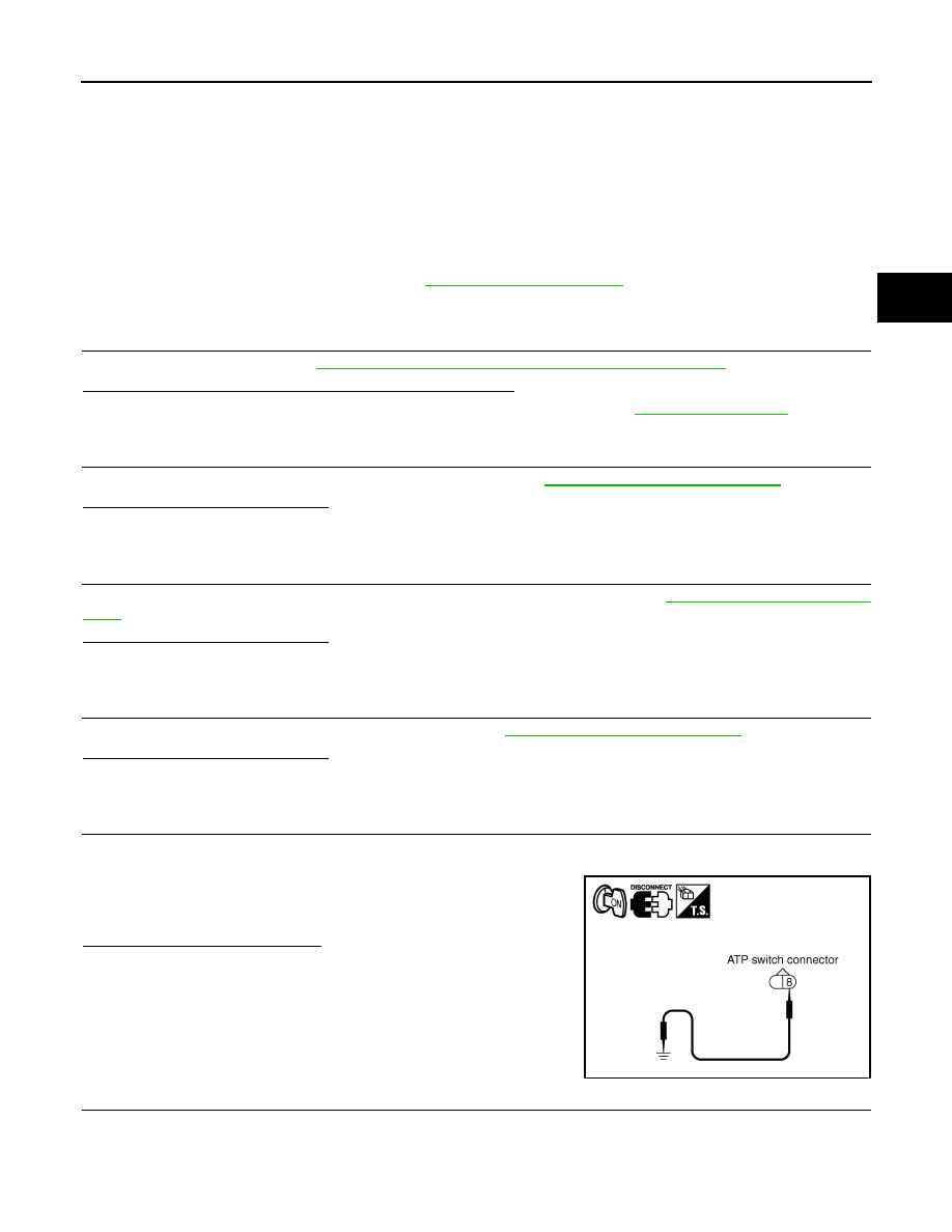
5.
CHECK ATP WARNING LAMP CIRCUIT
1. Disconnect ATP switch harness connector.
2. Turn ignition switch “ON”. (Do not start engine.)
3. Ground terminal 8 on ATP switch connector F71 using suitable
wiring.
4. Turn ignition switch “OFF”. (Stay for at least 5 seconds.)
Does ATP warning lamp turn on?
YES
>> GO TO 9.
NO
>> GO TO 6.
6.
CHECK HARNESS BETWEEN TRANSFER CONTROL UNIT AND COMBINATION METER
1. Turn ignition switch “OFF”. (Stay for at least 5 seconds.)
2. Disconnect transfer control unit harness connector and combination meter harness connector.
SDIA2832E
August 2012
2012 Pathfinder