Nissan Pathfinder (2012 year). Manual - part 189


  Index      Manuals     Nissan Pathfinder (2012 year) - Service and Repair Manual


Search            copyright infringement  


Content      ..     187      188      189      190     ..


Nissan Pathfinder (2012 year). Manual - part 189


P1827 CLUTCH PRESSURE SWITCH

DLN-77

< DTC/CIRCUIT DIAGNOSIS >

[TRANSFER: ATX14B]

C

E

F

G

H

I

J

K

L

M

A

B

DLN

N

O

P

P1827 CLUTCH PRESSURE SWITCH

Description

INFOID:0000000007357414

Improper signal from the clutch pressure switch is input due to open or short circuit.  Also, a malfunction may

have occurred in clutch pressure switch or hydraulic circuit.

DTC Logic

INFOID:0000000007357415

DTC DETECTION LOGIC

DTC CONFIRMATION PROCEDURE

1.

DTC CONFIRMATION PROCEDURE

1. Turn ignition switch ON.

2. Perform self-diagnosis.
Is DTC P1827 displayed?

YES

>> Perform diagnosis procedure. Refer to 

DLN-77, "Diagnosis Procedure"

.

NO

>> Inspection End.

Diagnosis Procedure

INFOID:0000000007357416

Regarding Wiring Diagram information, refer to 

DLN-100, "Wiring Diagram"

.

1.

CHECK CLUTCH PRESSURE SWITCH SIGNAL

With CONSULT

1. Start engine.

2. Select DATA MONITOR mode for ALL MODE AWD/4WD with CONSULT.

3. Read out ON/OFF switching action of the CL PRES SW while operating 4WD shift switch.
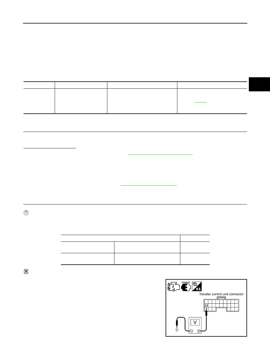
Without CONSULT

1. Start engine.

2. Check voltage between transfer control unit harness connector

terminals and ground.

DTC

CONSULT

Diagnostic item is detected when...

Reference

[P1827]

CLUTCH PRES SW

• Improper signal from clutch pressure 

switch is input due to open or short cir-
cuit.

• Malfunction occurs in clutch pressure 

switch or hydraulic circuit.

Refer to 

DLN-77

.

Condition

Display value

• Ignition switch: ON
• A/T selector lever D position

4WD shift switch: AUTO or 4H (Wait 
function is not operating.)

ON

Ignition switch: ON

4WD shift switch: 2WD (Wait function 
is not operating.)

OFF

SDIA2746E

August 2012

2012 Pathfinder

DLN-78

< DTC/CIRCUIT DIAGNOSIS >

[TRANSFER: ATX14B]

P1827 CLUTCH PRESSURE SWITCH

Are inspection results normal?

YES

>> GO TO 5.

NO

>> GO TO 2.

2.

CHECK HARNESS BETWEEN TRANSFER CONTROL UNIT AND CLUTCH PRESSURE SWITCH

1. Turn ignition switch OFF. (Stay for at least 5 seconds.)

2. Disconnect transfer control unit harness connector and the transfer terminal cord assembly harness con-

nector.

3. Check continuity between transfer control unit harness connec-

tor M153 terminal 34 and transfer terminal cord assembly har-

ness connector F56 terminal 7

Also check harness for short to ground and short to power.

Are inspection results normal?

YES 

>> GO TO 3.

NO

>> Repair or replace damaged parts.

3.

CHECK TRANSFER CONTROL UNIT

Check transfer control unit input/output signal. Refer to 

DLN-88, "Reference Value"

.

Are inspection results normal?

YES

>> GO TO 4.

NO

>> Check transfer control unit pin terminals for damage or loose connection with the harness connec-

tor. If any items are damaged, repair or replace damaged parts.

4.

CHECK CLUTCH PRESSURE SWITCH

1. Turn ignition switch OFF. (Stay for at least 5 seconds.)

2. Remove clutch pressure switch. Refer to 

DLN-19, "Component Parts Location"

.

3. Push and release clutch pressure switch and check continuity between terminal 7 and ground.

Are inspection results normal?

YES 

>> GO TO 5.

NO

>> Replace clutch pressure switch.

5.

CHECK DTC

Perform the self-diagnosis, after driving a vehicle for a while.
Are inspection results normal?

YES

>> GO TO 6.

NO

>> Replace transfer control unit. Refer to 

DLN-140, "Removal and Installation"

.

6.

CRUISE TEST

Connector

Terminal

Condition

Voltage 

(Approx.)

M153

34 - 

Ground

• Ignition switch: ON
• A/T selector lever D 

position

4WD shift switch: 
AUTO or 4H (Wait 
function is not op-
erating.)

0V

Ignition switch: ON

4WD shift switch: 
2WD (Wait function 
is not operating.)

Battery 
voltage

Continuity should exist.

SDIA2747E

Terminal

Condition

Continuity

7 - 

Ground

Push clutch pressure switch

Yes

Release clutch pressure switch

No

August 2012

2012 Pathfinder

P1827 CLUTCH PRESSURE SWITCH

DLN-79

< DTC/CIRCUIT DIAGNOSIS >

[TRANSFER: ATX14B]

C

E

F

G

H

I

J

K

L

M

A

B

DLN

N

O

P

Perform cruise test. Refer to 

DLN-10, "Preliminary Check"

.

Are inspection results normal?

YES

>> Inspection End.

NO

>> Perform the applicable trouble diagnosis.

Component Inspection

INFOID:0000000007357417

1. Turn ignition switch OFF. (Stay for at least 5 seconds.)
2. Remove clutch pressure switch. Refer to 

DLN-19, "Component Parts Location"

.

3. Push and release clutch pressure switch and check continuity between terminal 7 and ground.

4. If the inspection results are abnormal replace the clutch pressure switch.

Terminal

Condition

Continuity

7 - Ground

Push clutch pressure switch

Yes

Release clutch pressure switch

No

August 2012

2012 Pathfinder

DLN-80

< DTC/CIRCUIT DIAGNOSIS >

[TRANSFER: ATX14B]

P1828 LINE PRESSURE SWITCH

P1828 LINE PRESSURE SWITCH

Description

INFOID:0000000007357418

Improper signal from line pressure switch is input due to open or short circuit.  Also, a malfunction may have

occurred in the line pressure switch or hydraulic circuit.

DTC Logic

INFOID:0000000007357419

DTC DETECTION LOGIC

DTC CONFIRMATION PROCEDURE

1.

DTC CONFIRMATION PROCEDURE

1. Turn ignition switch ON.

2. Perform self-diagnosis.
Is DTC P1828 displayed?

YES

>> Perform diagnosis procedure. Refer to 

DLN-80, "Diagnosis Procedure"

.

NO

>> Inspection End.

Diagnosis Procedure

INFOID:0000000007357420

Regarding Wiring Diagram information, refer to 

DLN-100, "Wiring Diagram"

.

1.

CHECK LINE PRESSURE SWITCH SIGNAL

With CONSULT

1. Start engine.

2. Select DATA MONITOR mode for ALL MODE AWD/4WD with CONSULT.

3. Read out ON/OFF switching action of LINE PRES SW while operating 4WD shift switch.

Without CONSULT

1. Start engine.

DTC

CONSULT

Diagnostic item is detected when...

Reference

[P1828]

LINE PRES SW

• Improper signal from line pressure 

switch is input due to open or short cir-
cuit.

• Malfunction occurs in line pressure 

switch or hydraulic circuit.

Refer to 

DLN-80

.

Condition

Display value

• A/T selector lever D position
• 4WD shift switch: AUTO

ON

• Except the above
• The vehicle has been left 

at room temperature for 5 
minutes and more with ig-
nition switch in OFF posi-
tion.

• Ignition switch: ON
• A/T selector lever: P or N position
• 4WD shift switch: other than 

AUTO

OFF

August 2012

2012 Pathfinder

P1828 LINE PRESSURE SWITCH

DLN-81

< DTC/CIRCUIT DIAGNOSIS >

[TRANSFER: ATX14B]

C

E

F

G

H

I

J

K

L

M

A

B

DLN

N

O

P

2. Check voltage between transfer control unit harness connector

terminals and ground.

Are inspection results normal?

YES

>> GO TO 5.

NO

>> GO TO 2.

2.

CHECK HARNESS BETWEEN TRANSFER CONTROL UNIT AND LINE PRESSURE SWITCH

1. Turn ignition switch OFF. (Stay for at least 5 seconds.)

2. Disconnect transfer control unit harness connector and the transfer terminal cord assembly harness con-

nector.

3. Check continuity between transfer control unit harness connec-

tor M153 terminal 35 and transfer terminal cord assembly har-

ness connector F56 terminal 1.

Also check harness for short to ground and short to power.

Are inspection results normal?

YES 

>> GO TO 3.

NO

>> Repair or replace damaged parts.

3.

CHECK TRANSFER CONTROL UNIT

Check transfer control unit input/output signal. Refer to 

DLN-88, "Reference Value"

.

Are inspection results normal?

YES

>> GO TO 4.

NO

>> Check the following. If any items are damaged, repair or replace damaged parts.

• Transfer control unit pin terminals for damage or loose connection with harness connector.

• Transfer control unit. Refer to 

DLN-140, "Removal and Installation"

.

4.

CHECK LINE PRESSURE SWITCH

1. Turn ignition switch OFF. (Stay for at least 5 seconds.)

2. Remove line pressure switch. Refer to 

DLN-19, "Component Parts Location"

.

3. Push and release line pressure switch and check continuity between terminal 1 and ground.

Are inspection results normal?

YES 

>> GO TO 5.

NO

>> Replace line pressure switch.

5.

CHECK DTC

Perform the self-diagnosis, after driving a vehicle for a while.

Connector

Terminal

Condition

Voltage 

(Approx.)

M153

35 - 

Ground

• A/T selector lever D 

position

4WD shift switch:  
AUTO

0V

• Except the above
• The vehicle has 

been left at room 
temperature for 5 
minutes and more 
with ignition switch 
in OFF position.

• Ignition switch: 

ON

• A/T selector le-

ver: P or N posi-
tion

• 4WD shift 

switch: other 
than AUTO

Battery 
voltage

SDIA2751E

Continuity should exist.

SDIA2752E

Terminal

Condition

Continuity

1 - 

Ground

Push line pressure switch

Yes

Release line pressure switch

No

August 2012

2012 Pathfinder

DLN-82

< DTC/CIRCUIT DIAGNOSIS >

[TRANSFER: ATX14B]

P1828 LINE PRESSURE SWITCH

Are inspection results normal?

YES

>> GO TO 6.

NO

>> Replace transfer control unit.

6.

CRUISE TEST

Perform cruise test. Refer to 

DLN-10, "Preliminary Check"

.

Are inspection results normal?

YES

>> Inspection End.

NO

>> Perform the applicable trouble diagnosis.

Component Inspection

INFOID:0000000007357421

1. Turn ignition switch OFF. (Stay for at least 5 seconds.)
2. Remove line pressure switch. Refer to 

DLN-19, "Component Parts Location"

.

3. Push and release line pressure switch and check continuity between terminal 1 and ground.

4. If the inspection results are abnormal, replace the line pressure switch.

Terminal

Condition

Continuity

1 - Ground

Push line pressure switch

Yes

Release line pressure switch

No

August 2012

2012 Pathfinder

P1829 THROTTLE POSITION SIGNAL (ECM)

DLN-83

< DTC/CIRCUIT DIAGNOSIS >

[TRANSFER: ATX14B]

C

E

F

G

H

I

J

K

L

M

A

B

DLN

N

O

P

P1829 THROTTLE POSITION SIGNAL (ECM)

Description

INFOID:0000000007357422

Malfunction is detected in accelerator pedal position signal that is output from ECM through CAN communica-

tion.  Also, the signal voltage from accelerator pedal position sensor may be abnormally high or low.

DTC Logic

INFOID:0000000007357423

DTC DETECTION LOGIC

DTC CONFIRMATION PROCEDURE

1.

DTC CONFIRMATION PROCEDURE

1. Turn ignition switch ON.

2. Perform self-diagnosis.
Is DTC P1829 displayed?

YES

>> Perform diagnosis procedure. Refer to 

DLN-83, "Diagnosis Procedure"

.

NO

>> Inspection End.

Diagnosis Procedure

INFOID:0000000007357424

1.

CHECK DTC WITH ECM

Perform self-diagnosis with ECM. Refer to 

EC-533, "CONSULT Function"

.

Is any malfunction detected by self-diagnosis?

YES

>> Check the malfunctioning system.

NO

>> GO TO 2.

2.

CHECK TRANSFER CONTROL UNIT

Check transfer control unit input/output signal. Refer to 

DLN-88, "Reference Value"

.

Are inspection results normal?

YES

>> GO TO 3.

NO

>> Check transfer control unit pin terminals for damage or loose connection with harness connector.

If any items are damaged, repair or replace damaged parts.

3.

CHECK DTC

Perform the self-diagnosis, after driving a vehicle for a while.
Are inspection results normal?

YES

>> Inspection End.

NO

>> Perform self-diagnosis with ECM again.

DTC

CONSULT

Diagnostic item is detected when...

Reference

[P1829]

THROTTLE POSI SEN

• Malfunction is detected in accelerator 

pedal position signal that is output 
from ECM through CAN communica-
tion.

• Signal voltage from accelerator pedal 

position sensor is abnormally high or 
low.

Refer to 

DLN-83

.

August 2012

2012 Pathfinder

DLN-84

< DTC/CIRCUIT DIAGNOSIS >

[TRANSFER: ATX14B]

P1830 ABS OPERATION SIGNAL (ABS)

P1830 ABS OPERATION SIGNAL (ABS)

Description

INFOID:0000000007357425

Malfunction is detected in ABS operation signal that is output from ABS actuator and electric unit (control unit)

through CAN communication.

DTC Logic

INFOID:0000000007357426

DTC DETECTION LOGIC

DTC CONFIRMATION PROCEDURE

1.

DTC CONFIRMATION PROCEDURE

1. Turn ignition switch ON.

2. Perform self-diagnosis.
Is DTC P1830 displayed?

YES

>> Perform diagnosis procedure. Refer to 

DLN-84, "Diagnosis Procedure"

.

NO

>> Inspection End.

Diagnosis Procedure

INFOID:0000000007357427

1.

CHECK DTC WITH ABS ACTUATOR AND ELECTRIC UNIT (CONTROL UNIT)

Perform self-diagnosis with ABS actuator and electric unit (control unit). Refer to 

BRC-138, "CONSULT Func-

tion (ABS)"

.

Is any malfunction detected by self-diagnosis?

YES

>> Check the malfunctioning system.

NO

>> GO TO 2.

2.

CHECK TRANSFER CONTROL UNIT

Check transfer control unit input/output signal. Refer to 

DLN-88, "Reference Value"

.

Are the inspection results normal?

YES

>> GO TO 3.

NO

>> Check transfer control unit pin terminals for damage or loose connection with harness connector.

If any items are damaged, repair or replace damaged parts.

3.

CHECK DTC

Perform the self-diagnosis, after driving a vehicle for a while.
Are the inspection results normal?

YES

>> Inspection End.

NO

>> Perform self-diagnosis with ABS actuator and electric unit (control unit) again.

DTC

CONSULT

Diagnostic item is detected when...

Reference

[P1830]

ABS OP SIG

Malfunction is detected in ABS operation 
signal that is output from ABS actuator 
and electric unit (control unit) through 
CAN communication.

Refer to 

DLN-84

.

August 2012

2012 Pathfinder


Content      ..     187      188      189      190     ..