Nissan Pathfinder (2012 year). Manual - part 187


  Index      Manuals     Nissan Pathfinder (2012 year) - Service and Repair Manual


Search            copyright infringement  


Content      ..     185      186      187      188     ..


Nissan Pathfinder (2012 year). Manual - part 187


P1822 CLUTCH PRESSURE SOLENOID

DLN-61

< DTC/CIRCUIT DIAGNOSIS >

[TRANSFER: ATX14B]

C

E

F

G

H

I

J

K

L

M

A

B

DLN

N

O

P

Are the inspection results normal?

YES 

>> GO TO 7.

NO

>> GO TO 2.

2.

CHECK HARNESS BETWEEN TRANSFER CONTROL UNIT AND CLUTCH PRESSURE SOLENOID

VALVE

1. Turn ignition switch OFF. (Stay for at least 5 seconds.)

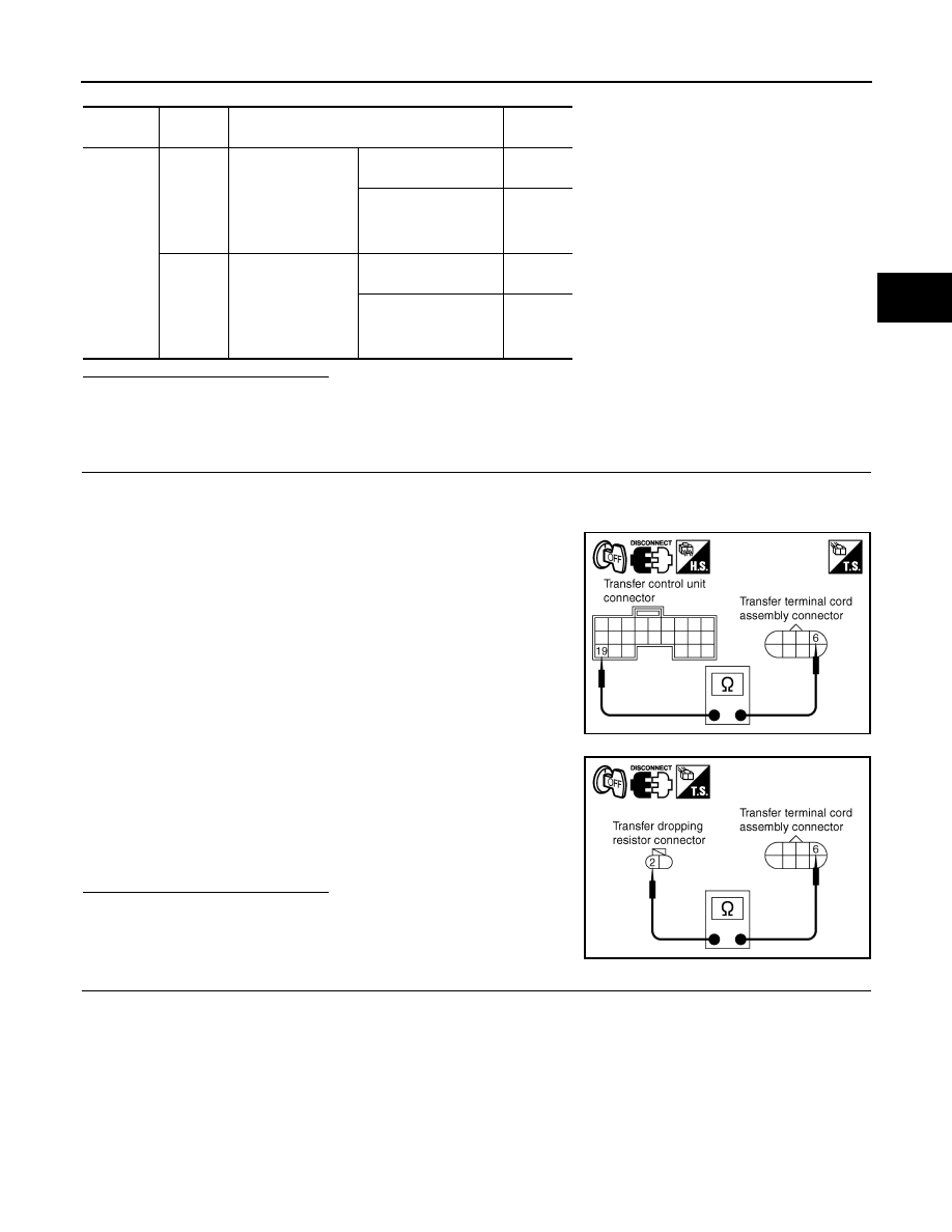
2. Disconnect transfer control unit harness connector, transfer terminal cord assembly harness connector

and transfer dropping resistor.

3. Check continuity between transfer control unit harness connec-

tor M152 terminal 19 and transfer terminal cord assembly har-

ness connector F56 terminal 6.

4. Check continuity between transfer dropping resistor harness

connector E135 terminal 2 and transfer terminal cord assembly

harness connector F56 terminal 6.

Also check harness for short to ground and short to power.

Are the inspection results normal?

YES

>> GO TO 3.

NO

>> Repair or replace damaged parts.

3.

CHECK HARNESS BETWEEN TRANSFER CONTROL UNIT AND TRANSFER DROPPING RESISTOR

1. Turn ignition switch OFF. (Stay for at least 5 seconds.)

2. Disconnect transfer control unit harness connector and transfer dropping resistor harness connector.

Connector

Terminal

Condition

Voltage 

(Approx.)

M152

 10 - 

Ground

• Vehicle stopped
• Engine running
• A/T selector lever 

N position

• Brake pedal de-

pressed

4WD shift switch: 
AUTO

4 - 14V

4WD shift switch: 
2WD, 4H or 4LO

Less than 
1V

 19 - 

Ground

• Vehicle stopped
• Engine running
• A/T selector lever 

N position

• Brake pedal de-

pressed

4WD shift switch: 
AUTO

1.5 - 3V

4WD shift switch: 
2WD, 4H or 4LO

Less than 
1V

Continuity should exist.

SDIA2720E

Continuity should exist.

SDIA2721E

August 2012

2012 Pathfinder

DLN-62

< DTC/CIRCUIT DIAGNOSIS >

[TRANSFER: ATX14B]

P1822 CLUTCH PRESSURE SOLENOID

3. Check continuity between transfer control unit harness connec-

tor M152 terminal 10 and transfer dropping resistor harness

connector E135 terminal 1.

Also check harness for short to ground and short to power.

Are the inspection results normal?

YES

>> GO TO 4.

NO

>> Repair or replace damaged parts.

4.

CHECK GROUND CIRCUIT

1. Turn ignition switch OFF. (Stay for at least 5 seconds.)

2. Disconnect transfer terminal cord assembly harness connector.

3. Check continuity between transfer terminal cord assembly har-

ness connector F56 terminal 19 and ground.

Also check harness for short to ground and short to power.

Are the inspection results normal?

YES 

>> GO TO 5.

NO

>> Repair open circuit or short to ground or short to power

in harness or connectors.

5.

CHECK CLUTCH PRESSURE SOLENOID

1. Turn ignition switch OFF. (Stay for at least 5 seconds.)

2. Disconnect transfer terminal cord assembly harness connector.

3. Check resistance between transfer terminal cord assembly har-

ness connector F56 terminals 6 and 19.

Are the inspection results normal?

YES

>> GO TO 6.

NO

>> Replace clutch pressure solenoid.  Refer to 

DLN-19,

"Component Parts Location"

.

6.

CHECK TRANSFER DROPPING RESISTOR

1. Turn ignition switch OFF. (Stay for at least 5 seconds.)

2. Disconnect transfer dropping resistor harness connector.

3. Check resistance between transfer dropping resistor terminals 1

and 2.

Are the inspection results normal?

YES

>> GO TO 7.

NO

>> Replace transfer dropping resistor.

7.

CHECK TRANSFER CONTROL UNIT

Check transfer control unit input/output signal. Refer to 

DLN-88, "Reference Value"

.

Continuity should exist.

SDIA2722E

Continuity should exist.

SDIA2723E

6 - 19

: Approx. 3.0 - 3.4 

WDIA0225E

1 - 2

: Approx. 11.2 - 12.8 

SDIA2725E

August 2012

2012 Pathfinder

P1822 CLUTCH PRESSURE SOLENOID

DLN-63

< DTC/CIRCUIT DIAGNOSIS >

[TRANSFER: ATX14B]

C

E

F

G

H

I

J

K

L

M

A

B

DLN

N

O

P

Are the inspection results normal?

YES

>> GO TO 8.

NO

>> Check transfer control unit pin terminals for damage or loose connection with harness connector.

If any items are damaged, repair or replace damaged parts.

8.

CHECK DTC

Drive the vehicle and then perform self-diagnosis.
Are the inspection results normal?

YES

>> Inspection End.

NO

>> Replace transfer control unit. Refer to 

DLN-140, "Removal and Installation"

.

Component Inspection

INFOID:0000000007357401

CLUTCH PRESSURE SOLENOID

1. Turn ignition switch OFF. (Stay for at least 5 seconds.)
2. Disconnect transfer terminal cord assembly harness connector.
3. Check resistance between transfer terminal cord assembly ter-

minals 6 and 19.

4. If the inspection results are abnormal replace clutch pressure

solenoid. Refer to 

DLN-19, "Component Parts Location"

.

TRANSFER DROPPING RESISTOR

1. Turn ignition switch OFF. (Stay for at least 5 seconds.)
2. Disconnect transfer dropping resistor harness connector.
3. Check resistance between transfer dropping resistor terminals 1

and 2.

4. If the inspection results are abnormal replace transfer dropping

resistor. Refer to 

DLN-19, "Component Parts Location"

.

6 - 19

: Approx. 3.0 - 3.4 

WDIA0225E

1 - 2

: Approx. 11.2 - 12.8 

SDIA2725E

August 2012

2012 Pathfinder

DLN-64

< DTC/CIRCUIT DIAGNOSIS >

[TRANSFER: ATX14B]

P1823 2-4 SOLENOID

P1823 2-4 SOLENOID

Description

INFOID:0000000007357402

Proper voltage is not applied to the 2-4WD solenoid valve due to an open or short circuit.

DTC Logic

INFOID:0000000007357403

DTC DETECTION LOGIC

DTC CONFIRMATION PROCEDURE

1.

DTC CONFIRMATION PROCEDURE

1. Turn ignition switch ON.

2. Perform self-diagnosis.
Is DTC P1823 displayed?

YES

>> Perform diagnosis procedure. Refer to 

DLN-64, "Diagnosis Procedure"

.

NO

>> Inspection End.

Diagnosis Procedure

INFOID:0000000007357404

Regarding Wiring Diagram information, refer to 

DLN-100, "Wiring Diagram"

.

1.

CHECK 4WD SHIFT SWITCH SYSTEM

Perform self-diagnosis.  Refer to 

DLN-23, "CONSULT Function (ALL MODE AWD/4WD)"

.

Is the "4WD MOD SW [P1814]" (with CONSULT) or "Flickering pattern:16" (without CONSULT) detected?

YES

>> Perform trouble diagnosis for 4WD shift switch.  Refer to 

DLN-38, "Diagnosis Procedure"

.

NO

>> GO TO 2

2.

CHECK 2-4WD SHIFT SOLENOID SIGNAL

With CONSULT

1. Start engine.

2. Select “DATA MONITOR” mode for “ALL MODE AWD/4WD” with CONSULT.

3. Read out the value of “2-4WD SOL” and “2-4WD SOL MON”.

DTC

CONSULT

Diagnostic item is detected when...

Reference

[P1823]

2-4WD SOLENOID

Proper voltage is not applied to 2-4WD 
solenoid valve due to open or short cir-
cuit.

Refer to 

DLN-64

.

Monitored 

item

Condition

Display 

value

2-4WD SOL

• Vehicle stopped
• Engine running
• A/T selector lever “N” 

position

• Brake pedal de-

pressed

4WD shift switch: 2WD

OFF

4WD shift switch: AUTO

ON

4WD shift switch: 4H

4WD shift switch: 4LO

4WD shift switch: AUTO 
(“Wait” function is operating.)

OFF

4WD shift switch: 4H (“Wait” 
function is operating.)

OFF

August 2012

2012 Pathfinder

P1823 2-4 SOLENOID

DLN-65

< DTC/CIRCUIT DIAGNOSIS >

[TRANSFER: ATX14B]

C

E

F

G

H

I

J

K

L

M

A

B

DLN

N

O

P

Without CONSULT

1. Start engine.

2. Check voltage between transfer control unit harness connector

terminal and ground.

OK or NG

OK 

>> GO TO 7.

NG

>> GO TO 3.

3.

CHECK 4WD SHIFT SWITCH SIGNAL

1. Turn ignition switch “ON”. (Do not start engine.)

2. Check voltage between transfer control unit harness connector

terminals and ground.

OK or NG

OK 

>> GO TO 4.

NG

>> Check 4WD shift switch.  Refer to 

DLN-40, "Component Inspection"

.

4.

CHECK HARNESS BETWEEN 4WD SHIFT SWITCH AND TRANSFER TERMINAL CORD ASSEMBLY

1. Turn ignition switch “OFF”.  (Stay for at least 5 seconds.)

2. Disconnect 4WD shift switch harness connector and transfer terminal cord assembly harness connector.

2-4WD SOL 
MON

• Vehicle stopped
• Engine running
• A/T selector lever “N” 

position

• Brake pedal de-

pressed

4WD shift switch: 2WD

OFF

4WD shift switch: AUTO

ON

4WD shift switch: 4H

4WD shift switch: 4LO

4WD shift switch: AUTO 
(“Wait” function is operating.)

OFF

4WD shift switch: 4H (“Wait” 
function is operating.)

OFF

Monitored 

item

Condition

Display 

value

Connector

Terminal

Condition

Voltage 

(Approx.)

M152

 1 - 

Ground

• Vehicle stopped
• Engine running
• A/T selector lever 

“N” position

• Brake pedal de-

pressed

4WD shift switch: 2WD 0V

4WD shift switch: AU-
TO, 4H or 4LO

Battery 
voltage

SDIA2728E

Connector

Terminal

Condition

Voltage (Ap-

prox.)

M141

4 - ground

4WD shift switch: AUTO, 4H or 4LO Battery voltage

4WD shift switch: 2WD

0V

SDIA2729E

August 2012

2012 Pathfinder

DLN-66

< DTC/CIRCUIT DIAGNOSIS >

[TRANSFER: ATX14B]

P1823 2-4 SOLENOID

3. Check continuity between 4WD shift switch harness connector

M141 terminal 4 and transfer terminal cord assembly harness

connector F56 terminal 5.

Also check harness for short to ground and short to power.

OK or NG

OK

>> GO TO 5.

NG

>> Repair or replace damaged parts.

5.

CHECK HARNESS BETWEEN TRANSFER CONTROL UNIT AND TRANSFER TERMINAL CORD AS-

SEMBLY
1. Turn ignition switch “OFF”.  (Stay for at least 5 seconds.)

2. Disconnect transfer control unit harness connector and transfer terminal cord assembly harness connec-

tor.

3. Check continuity between transfer control unit harness connec-

tor M152 terminal 1 and transfer terminal cord assembly har-

ness connector F56 terminal 4.

Also check harness for short to ground and short to power.

OK or NG

OK

>> GO TO 6.

NG

>> Repair or replace damaged parts.

6.

CHECK 2-4WD SOLENOID

1. Turn ignition switch “OFF”.  (Stay for at least 5 seconds.)

2. Disconnect transfer terminal cord assembly harness connector.

3. Check resistance between transfer terminal cord assembly ter-

minals 4 and 5.

OK or NG

OK

>> GO TO 7.

NG

>> 2-4WD solenoid is malfunctioning. Refer to 

DLN-19,

"Component Parts Location"

.

7.

CHECK TRANSFER CONTROL UNIT

Check transfer control unit input/output signal. Refer to 

DLN-88, "Reference Value"

.

OK or NG

OK

>> GO TO 8.

NG

>> Check transfer control unit pin terminals for damage or loose connection with harness connector.

If any items are damaged, repair or replace damaged parts.

8.

CHECK DTC

Perform the self-diagnosis, after driving a vehicle for a while.
OK or NG

OK

>> Inspection End.

NG

>> Replace transfer control unit. Refer to 

DLN-140, "Removal and Installation"

.

Continuity should exist.

SDIA2731E

Continuity should exist.

SDIA2732E

4 - 5

: Approx. 22.8 - 25.2 

SDIA3253E

August 2012

2012 Pathfinder

P1823 2-4 SOLENOID

DLN-67

< DTC/CIRCUIT DIAGNOSIS >

[TRANSFER: ATX14B]

C

E

F

G

H

I

J

K

L

M

A

B

DLN

N

O

P

Component Inspection

INFOID:0000000007357405

1. Turn ignition switch “OFF”.  (Stay for at least 5 seconds.)
2. Disconnect transfer terminal cord assembly harness connector.
3. Check resistance between transfer terminal cord assembly ter-

minals 4 and 5.

4. If NG, replace the 2-4WD solenoid. Refer to 

DLN-19, "Compo-

nent Parts Location"

.

4 - 5

: Approx. 22.8 - 25.2 

SDIA3253E

August 2012

2012 Pathfinder

DLN-68

< DTC/CIRCUIT DIAGNOSIS >

[TRANSFER: ATX14B]

P1824 TRANSFER MOTOR

P1824 TRANSFER MOTOR

Description

INFOID:0000000007357406

Motor does not operate properly due to open or short circuit in transfer motor or transfer motor relay.

DTC Logic

INFOID:0000000007357407

DTC DETECTION LOGIC

DTC CONFIRMATION PROCEDURE

1.

DTC CONFIRMATION PROCEDURE

1. Turn ignition switch ON.

2. Perform self-diagnosis.
Is DTC P1824 displayed?

YES

>> Perform diagnosis procedure. Refer to 

DLN-68, "Diagnosis Procedure"

.

NO

>> Inspection End.

Diagnosis Procedure

INFOID:0000000007357408

Regarding Wiring Diagram information, refer to 

DLN-100, "Wiring Diagram"

.

1.

CHECK TRANSFER MOTOR RELAY SIGNAL

With CONSULT

1. Start engine.

2. Select “DATA MONITOR” mode for “ALL MODE AWD/4WD” with CONSULT.

3. Read out the value of “MOTOR RELAY” and “MOTOR RELAY MON”.

DTC

CONSULT

Diagnostic item is detected when...

Reference

[P1824]

MOTOR RELAY

Motor does not operate properly due to 
open or short circuit in transfer motor or 
transfer motor relay.

Refer to 

DLN-68

.

Monitored 

item

Condition

Display value

(Approx.)

MOTOR 
RELAY

• Accelerator ped-

al depressed

• Vehicle stopped
• Engine running
• Brake pedal de-

pressed

4WD shift switch: 2WD

OFF

4WD shift switch: AUTO or 
4LO (A/T selector lever “P” or 
“N” position)

OFF
("ON" for ap-
prox. 2 sec. af-
ter shifting to 
“P” and “N”.)

4WD shift switch: AUTO or 
4LO (Except for A/T selector 
lever “P” or “N” position)

ON

4WD shift switch: 4H (A/T se-
lector lever “P” position)

OFF
("ON" for ap-
prox. 2 sec. af-
ter shifting to 
“P”.)

4WD shift switch: 4H (Except 
for A/T selector lever “P” posi-
tion)

ON

August 2012

2012 Pathfinder


Content      ..     185      186      187      188     ..