Nissan Pathfinder (2011 year). Manual - part 605


  Index      Manuals     Nissan Pathfinder (2011 year) - Service and Repair Manual


Search            copyright infringement  


Content      ..     603      604      605      606     ..


Nissan Pathfinder (2011 year). Manual - part 605


TM-186

< REMOVAL AND INSTALLATION >

KEY INTERLOCK CABLE

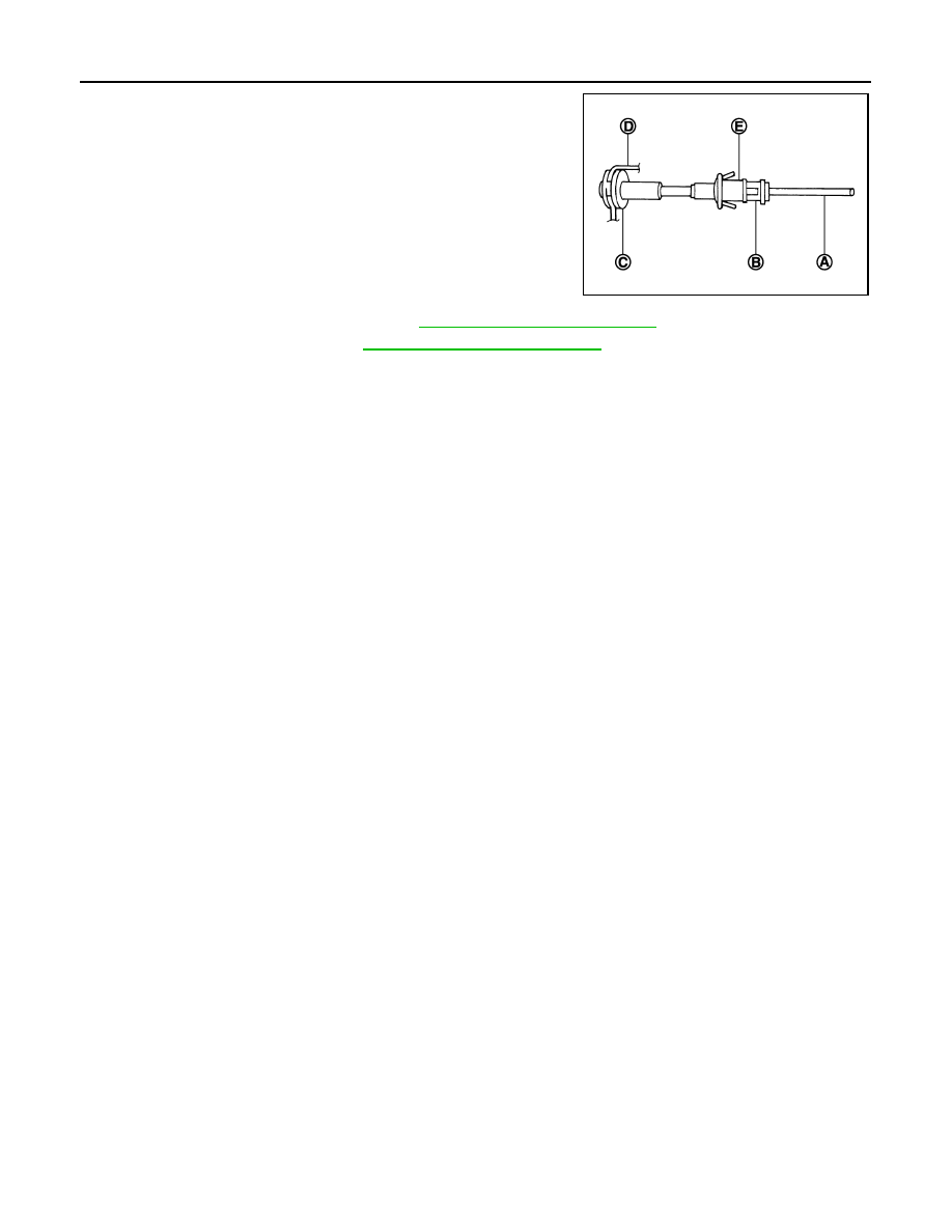
4. Insert key interlock rod (A) into adjuster holder (B).
5. Install casing cap (C) to bracket (D).
6. Move slider (E) toward key interlock rod (A) to secure adjuster

holder (B) to key interlock rod (A).

7. Install instrument lower panel LH. Refer to 

IP-12, "Removal and Installation"

.

8. Install the center console. Refer to 

IP-21, "Removal and Installation"

.

JSDIA0698ZZ

2011 Pathfinder

AIR BREATHER HOSE

TM-187

< REMOVAL AND INSTALLATION >

C

E

F

G

H

I

J

K

L

M

A

B

TM

N

O

P

AIR BREATHER HOSE

2WD
2WD : Removal and Installation

INFOID:0000000006244882

VQ40DE Models

REMOVAL

1. Release air breather hose from clip.
2. Disconnect air breather hose from transmission tube.
3. Disconnect air breather hose from air breather tube.

INSTALLATION

Installation is in the reverse order of removal.

CAUTION:

• Install air breather hose with paint mark at upper side.

• When installing the air breather hose, do not crush or block by folding or bending the hose.

• When inserting the hose to the transmission tube, be sure to insert it fully until its end reaches the

tube bend portion.

• Make sure clip is securely installed to bracket.

4WD
4WD : Removal and Installation

INFOID:0000000006244883

VQ40DE Models

1.

Air breather hose

2.

Transmission assembly

A.

Paint mark

B.

Clip

WCIA0663E

2011 Pathfinder

TM-188

< REMOVAL AND INSTALLATION >

AIR BREATHER HOSE

REMOVAL

1. Release air breather hose from clip.
2. Disconnect air breather hose from transmission tube.
3. Disconnect air breather hose from air breather tube.

INSTALLATION

Installation is in the reverse order of removal.

CAUTION:

• Install air breather hose with paint mark at upper side.

• When installing an air breather hose, do not crush or block by folding or bending the hose.

• When inserting a hose to the transmission tube, be sure to insert it fully until its end reaches the

tube bend portion.

• Make sure clip is securely installed to bracket.

1.

Air breather hose

2.

Transmission assembly

A.

Paint mark

B.

Clip

WCIA0664E

2011 Pathfinder

AIR BREATHER HOSE

TM-189

< REMOVAL AND INSTALLATION >

C

E

F

G

H

I

J

K

L

M

A

B

TM

N

O

P

VK56DE Models

REMOVAL

1. Release air breather hose from clip.
2. Disconnect air breather hose from transmission tube.
3. Disconnect air breather hose from air breather tube.

INSTALLATION

CAUTION:

Make sure there are no pinched or restricted areas on each air breather hose caused by folding or

bending when installing it.

1. Install each air breather hose into the breather tube (4). Set

each air breather hose with paint mark facing upward. 

• A/T breather hose (1)

• Transfer breather hose (2)

• Actuator/transfer motor breather hose (3)

• Paint marks (A)

2. Install actuator/transfer motor air breather hose (1) and transfer

air breather hose (2) on clip (A) with the paint mark (B) facing

upward.

:Front

AWDIA0010ZZ

1.

Breather tube

2.

Clip A

3.

Clip B

4.

Clip C

5.

Clip D

6.

Actuator

7.

Air breather hose clamp

8.

 Clip E

9.

Transfer motor

10. Breather tube (transfer)

Vehicle front

ALDIA0110ZZ

ALDIA0111ZZ

2011 Pathfinder

TM-190

< REMOVAL AND INSTALLATION >

AIR BREATHER HOSE

3. Install clip (B) on actuator/transfer motor air breather hose (1)

and transfer air breather hose (2) with the paint mark (A)

matched.

:Front

4. Install actuator/transfer motor air breather hose (1) and transfer

air breather hose (2) on clip (B) and clip (C) with the paint mark

(A) and (D) facing upward.

:Front

5. Install the actuator air breather hose into the actuator (case con-

nector) until the hose end reaches the base of the tube. Set

actuator air breather hose with paint mark facing leftward.

6. Install clip (B) on transfer motor air breather hose (2) and trans-

fer air breather hose (1) with the paint mark (A) matched.

:Front

7. Install the transfer air breather hose into the breather tube

(transfer, metal connector) until the hose end reaches the base

of the tube. Set transfer air breather hose with paint mark facing

upwards.

AWDIA0011ZZ

AWDIA0012ZZ

SDIA3226E

AWDIA0013ZZ

SDIA3196E

2011 Pathfinder

AIR BREATHER HOSE

TM-191

< REMOVAL AND INSTALLATION >

C

E

F

G

H

I

J

K

L

M

A

B

TM

N

O

P

8. Install the transfer motor air breather hose into the transfer

motor (case connector) until the hose end reaches the end of

the curved section. Set transfer motor air breather hose with

paint mark facing leftward.

SDIA3194E

2011 Pathfinder

TM-192

< REMOVAL AND INSTALLATION >

A/T FLUID COOLER

A/T FLUID COOLER

Removal and Installation

INFOID:0000000006244884

REMOVAL

NOTE:

When removing components such as hoses, tubes/lines, etc., cap or plug openings to prevent fluid from spill-

ing.
1. Remove front grill. Refer to 

EXT-20, "Removal and Installation"

.

2. Remove A/T fluid cooler hoses from fluid cooler.
3. Remove A/T fluid cooler.

INSTALLATION

Installation is in the reverse order of removal.

• After completing installation, check fluid level and check for fluid leakage. Refer to 

TM-155, "Checking the A/

T Fluid (ATF)"

.

1.

A/T fluid cooler

2.

Fluid cooler tube

3.

Clip

4.

Hose clamp

5.

Cooler hose (lower)

6.

Cooler hose

7.

Tube joint

8.

Cooler hose (upper)

A.

To transmission

B.

From radiator

AWDIA0624GB

2011 Pathfinder

TRANSMISSION ASSEMBLY

TM-193

< UNIT REMOVAL AND INSTALLATION >

C

E

F

G

H

I

J

K

L

M

A

B

TM

N

O

P

UNIT REMOVAL AND INSTALLATION

TRANSMISSION ASSEMBLY

2WD
2WD : Exploded View

INFOID:0000000006244885

2WD : Removal and Installation

INFOID:0000000006244886

REMOVAL

CAUTION:

When removing the A/T assembly from engine, first remove the crankshaft position sensor (POS) from

the A/T assembly.

NOTE:

When removing components such as hoses, tubes/lines, etc., cap or plug openings to prevent fluid from spill-

ing.
1. Disconnect the negative battery terminal.
2. Remove the A/T fluid level gauge.
3. Remove front LH wheel and tire assembly. Refer to 

WT-50, "Adjustment"

.

4. Remove the front LH mud flap. Refer to 

EXT-27, "Removal and Installation"

.

5. Remove the LH fender protector. Refer to 

EXT-25, "Removal and Installation of Front Fender Protector"

.

AWDIA0622GB

1.

A/T fluid level gauge

2.

A/T fluid charging pipe

3.

O-ring

4.

Insulator

5.

A/T crossmember

6.

Copper sealing washer

7.

Bracket

8.

A/T fluid cooler tube

9.

Front crossmember

10. Transmission assembly

A. Self-sealing bolt

B. Refer to installation.

2011 Pathfinder


Content      ..     603      604      605      606     ..