Nissan Pathfinder (2011 year). Manual - part 389


  Index      Manuals     Nissan Pathfinder (2011 year) - Service and Repair Manual


Search            copyright infringement  


Content      ..     387      388      389      390     ..


Nissan Pathfinder (2011 year). Manual - part 389


CYLINDER HEAD

EM-223

< REMOVAL AND INSTALLATION >

[VK56DE]

C

D

E

F

G

H

I

J

K

L

M

A

EM

N

P

O

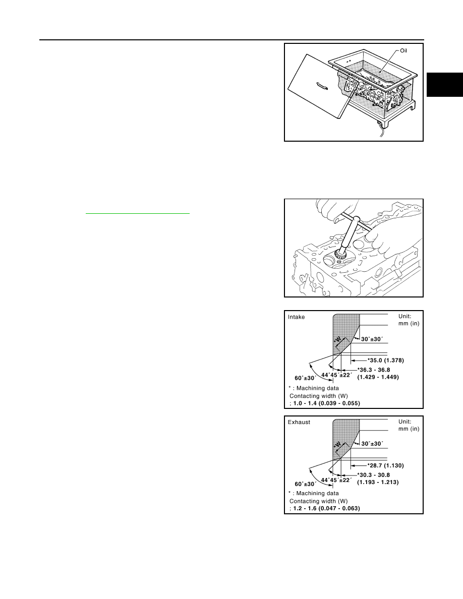
3. Heat the cylinder head to 110

°

 to 130

°

C (230

°

 to 266

°

F) by

soaking it in heated oil.

4. Cool the valve seats well with dry ice. Force fit the valve seat into the cylinder head.

WARNING:

• Cylinder head contains heat. When working, wear protective equipment to avoid getting burned.

CAUTION:

• Avoid directly touching cold valve seats.

5. Finish the seat to the specified dimensions using suitable tool.

Refer to 

EM-255, "Standard and Limit"

.

CAUTION:

When using valve seat cutter, firmly grip the cutter handle

with both hands. Then, press on the contacting surface all

around the circumference to cut in a single drive. Improper

pressure on the cutter or cutting many different times may

result in stage valve seat. 

6. Grind to obtain the dimensions indicated as shown.

• Using compound, grind to adjust valve fitting. 

7. Check again for normal contact.

VALVE SPRING SQUARENESS

SEM008A

SEM934C

KBIA2531E

KBIA2544E

2011 Pathfinder

EM-224

< REMOVAL AND INSTALLATION >

[VK56DE]

CYLINDER HEAD

• Set try square along the side of valve spring and rotate the spring.

Measure the maximum clearance between the top face of spring

and try square.

• If measurement is not within specifications, replace the valve

spring.

VALVE SPRING DIMENSIONS AND VALVE SPRING PRESSURE LOAD

• Check the valve spring pressure at the specified spring height.

• If measurement is not within specifications, replace the valve spring.

Limit

: Less than 2.2 mm (0.087 in)

PBIC0080E

Standard:

Intake and exhaust

Free height:

50.58 mm (1.9913 in)

Installation height:

37.0 mm (1.457 in)

Installation pressure:

165.8 - 187.0 N (16.9 - 
19.1 kg, 37- 42 lb)

Height during valve open: 28.2 mm (1.110 in)
Load with valve open:

314.8 - 355.0 N (32.1 - 
36.2 kg, 71 - 80 lb)

SEM113

2011 Pathfinder

ENGINE ASSEMBLY

EM-225

< UNIT REMOVAL AND INSTALLATION >

[VK56DE]

C

D

E

F

G

H

I

J

K

L

M

A

EM

N

P

O

UNIT REMOVAL AND INSTALLATION

ENGINE ASSEMBLY

Exploded View

INFOID:0000000006247098

Removal and Installation

INFOID:0000000006247099

WARNING:

• Situate vehicle on a flat and solid surface.

• Place chocks at front and back of rear wheels.

• For engines not equipped with engine slingers, attach proper slingers and bolts described in PARTS

CATALOG.

CAUTION:

• Always be careful to work safely, avoid forceful or uninstructed operations.

• Do not start working until exhaust system and engine coolant are cooled sufficiently.

• If items or work required are not covered by the engine section, follow the applicable procedures.

• Always use the support point specified for lifting.

• Use either 2-point lift type or separate type lift. If board-on type is used for unavoidable reasons,

support at the rear axle jacking point with transmission jack or similar tool before starting work, in

preparation for the backward shift of center of gravity.

• For supporting points for lifting and jacking point at rear axle, refer to 

GI-29, "Garage Jack and

Safety Stand"

.

NOTE:

When removing components such as hoses, tubes/lines, etc., cap or plug openings to prevent fluid from spill-

ing.

1.

Rear engine mounting insulator 

2.

RH heat shield plate

3.

RH engine mounting insulator

4.

RH engine mounting bracket

5.

LH engine mounting insulator

6.

LH engine mounting bracket

7.

LH heat shield plate

A. Refer to installation

Front

AWBIA0863GB

2011 Pathfinder

EM-226

< UNIT REMOVAL AND INSTALLATION >

[VK56DE]

ENGINE ASSEMBLY

REMOVAL

Preparation

1. Release the fuel pressure. Refer to 

EC-938, "Fuel Pressure Check"

.

2. Disconnect the battery negative terminal and disconnect the batter negative harness from the engine.

Refer to 

PG-76, "Removal and Installation"

.

3. Remove engine under cover (front and rear) and transfer case under cover. Refer to 

EXT-15, "Removal

and Installation"

.

4. Drain the engine coolant. Refer to 

CO-44, "Changing Engine Coolant"

.

5. Partially drain the transmission fluid. Refer to 

TM-157, "Changing the A/T Fluid (ATF)"

6. Partially drain the transfer case fluid. Refer to 

DLN-136, "Replacement"

.

7. Remove the engine hood. Refer to 

DLK-193, "Removal and Installation of Hood Assembly"

.

8. Remove the engine room cover using power tool. Refer to 

EM-164, "Removal and Installation"

.

9. Disconnect the vacuum hose between the vehicle and engine and set it aside.
10. Remove the radiator assembly and hoses. Refer to 

CO-49, "Removal and Installation"

.

11. Remove the drive belt. Refer to 

EM-153, "Removal and Installation"

.

12. Remove the fan blade. Refer to 

CO-52, "Removal and Installation (Crankshaft Driven Type)"

.

13. Remove the battery positive harness.
14. Disconnect the engine room harness from the fuse box and set it aside.
15. Disconnect the ECM.
16. Disconnect the engine room harness from the engine side and set it aside.
17. Disconnect the engine harness grounds.
18. Disconnect the power steering reservoir tank from the engine and move it aside.
19. Disconnect the power steering oil pump from the engine. Move it aside and secure it using suitable wire or

rope. Refer to 

ST-24, "Removal and Installation"

.

20. Remove the A/C compressor bolts and set the compressor aside. Refer to 

HA-38, "Removal and Installa-

tion for Compressor"

.

21. Disconnect the brake booster vacuum line.
22. Disconnect the EVAP line.
23. Disconnect the fuel hose at the engine side connection. Refer to 

EM-181, "Removal and Installation"

.

24. Disconnect the heater hoses at the cowl and engine. 
25. Remove the engine and transmission oil level indicators and indicator tubes. 
26. Remove the front fender protectors. Refer to 

EXT-25, "Removal and Installation of Front Fender Protec-

tor"

.

27. Remove the front final drive assembly. Refer to 

DLN-390, "Removal and Installation"

.

28. Remove the exhaust manifolds. Refer to 

EM-170, "Removal and Installation"

.

29. Remove the A/T. Refer to 

TM-197, "4WD : Removal and Installation"

.

30. Install the engine slingers into the left bank cylinder head (A)

and right bank cylinder head (B).

31. Lift using a hoist and secure the engine in position.
32. Remove engine mounting insulator bolts.
33. Remove the engine assembly from the vehicle, avoid interfer-

ence with the vehicle body.

CAUTION:

• Before and during lifting, always check if any harnesses

are left connected.

34. Remove the parts that may restrict installation of the engine to the engine stand.

NOTE:

This procedure is described based on the use of an engine stand mounting to the surface on which the

transmission mounts.

Engine slinger torque:

45.0 N·m (4.6 kg-m, 33 ft-lb)

AWBIA0088ZZ

2011 Pathfinder

ENGINE ASSEMBLY

EM-227

< UNIT REMOVAL AND INSTALLATION >

[VK56DE]

C

D

E

F

G

H

I

J

K

L

M

A

EM

N

P

O

a. Before removing the drive plate, put a match mark (A) on the

crankshaft and drive plate for alignment during installation.

b. Remove the drive plate.

• Holding the crankshaft pulley bolt, lock the crankshaft to

remove the drive plate bolts.

• Remove drive plate bolts diagonally.

CAUTION:

• Do not damage the drive plate. Especially, avoid deform-

ing and damaging the signal plate teeth (circumference

position).

• Keep magnetic materials away from signal plate.

• Place the drive plate with the signal plate surface facing

upward.

CAUTION:

Use an engine stand that has a load capacity [approximately 240kg (529 lb) or more] large enough

for supporting the engine weight.

• If the load capacity of the stand is not adequate, remove the following parts beforehand to

reduce the potential risk of overturning the stand.

- Remove the fuel tube and fuel injector assembly. Refer to 

EM-181, "Removal and Installation"

.

- Remove the intake manifold. Refer to 

EM-166, "Removal and Installation"

.

- Remove the ignition coil. Refer to 

EM-178, "Removal and Installation"

.

- Remove the rocker cover. Refer to 

EM-179, "Removal and Installation"

.

- Other removable brackets.

CAUTION:

Before removing the hanging chains, make sure the engine stand is stable and there is no risk of

overturning.

35. Remove the generator, if necessary. Refer to 

CHG-21, "Removal and Installation"

.

36. Remove the engine mounting insulator and bracket using power tool.

INSTALLATION

Installation is in the reverse order of removal.

• Tighten engine mounting bracket bolts in numerical order as

shown.

CAUTION:

• When replacing an engine or transmission you must make sure the dowels are installed correctly

during re-assembly.

ALBIA0522ZZ

KBIA2491E

Engine mounting bracket 
bolts

: 49 N·m (5.0 kg-m, 36 ft-lb)

AWBIA0820ZZ

2011 Pathfinder

EM-228

< UNIT REMOVAL AND INSTALLATION >

[VK56DE]

ENGINE ASSEMBLY

• Improper alignment caused by missing dowels may cause vibration, oil leaks or breakage of driv-

etrain components.

INSPECTION AFTER INSTALLATION

• Before starting engine, check oil/fluid levels including engine coolant and engine oil. If less than required

quantity, fill to the specified level. Refer to 

MA-18, "FOR USA AND CANADA : Fluids and Lubricants"

 (United

States and Canada).

• Use procedure below to check for fuel leakage.

• Turn ignition switch ON (with engine stopped). With fuel pressure applied to fuel piping, check for fuel leak-

age at connection points.

• Start engine. With engine speed increased, check again for fuel leakage at connection points.

• Run engine to check for unusual noise and vibration.

NOTE:

If hydraulic pressure inside timing chain tensioner drops after removal and installation, slack in the guide

may generate a pounding noise during and just after engine start. However, this is normal. Noise will stop

after hydraulic pressure rises.

• Warm up engine thoroughly to make sure there is no leakage of fuel, exhaust gas, or any oils/fluids including

engine oil and engine coolant.

• Bleed air from passages in lines and hoses, such as in cooling system.

• After cooling down engine, again check oil/fluid levels including engine oil and engine coolant. Refill to spec-

ified level, if necessary.

• Summary of the inspection items:

*Power steering fluid, brake fluid, etc.

Item

Before starting engine

Engine running

After engine stopped

Engine coolant

Level

Leakage

Level

Engine oil

Level

Leakage

Level

Transmission/
transaxle fluid 

A/T and CVT Models

Leakage

Level/Leakage

Leakage

M/T Models

Level/Leakage

Leakage

Level/Leakage

Other oils and fluids*

Level

Leakage

Level

Fuel

Leakage

Leakage

Leakage

Exhaust gas

Leakage

2011 Pathfinder

ENGINE UNIT

EM-229

< UNIT DISASSEMBLY AND ASSEMBLY >

[VK56DE]

C

D

E

F

G

H

I

J

K

L

M

A

EM

N

P

O

UNIT DISASSEMBLY AND ASSEMBLY

ENGINE UNIT

Exploded View

INFOID:0000000006247100

1.

Knock sensor sub-harness

2.

 Knock sensor

3.

Cylinder block

4.

Main bearing upper

5.

Top ring

6.

Second ring

7.

Oil ring

8.

Crankshaft key

9.

Piston

10. Connecting rod

11.

Snap ring

12.

Piston pin

13. Connecting rod bearing

14.

Connecting rod bearing cap

15.

Main bearing cap

AWBIA0455GB

2011 Pathfinder

EM-230

< UNIT DISASSEMBLY AND ASSEMBLY >

[VK56DE]

ENGINE UNIT

Disassembly and Assembly

INFOID:0000000006247101

DISASSEMBLY

NOTE:

Explained here is how to disassemble with engine stand supporting transmission surface. When using differ-

ent type of engine stand, some steps may be different.
1. Remove engine assembly from vehicle and mount to engine stand. Refer to 

EM-225, "Removal and

Installation"

.

CAUTION:

Before removing the hanging chains, make sure engine stand is stable and there is no risk of over-

turning.

2. Drain engine coolant by removing the cylinder block drain plugs

(A), (B), (C) and (D) as shown.

3. Remove the following components and associated parts.

• Oil pan (upper and lower) and oil strainer. Refer to 

EM-173, "Removal and Installation"

.

• Crankshaft pulley, front cover and timing chain. Refer to 

EM-195, "Removal and Installation"

.

• Camshaft. Refer to 

EM-200, "Removal and Installation"

.

• Cylinder head. Refer to 

EM-215, "Removal and Installation"

.

4. Remove knock sensor and sub harness.

CAUTION:

Carefully handle sensor, avoiding shocks.

5. Check connecting rod side clearance. Refer to 

EM-237, "Inspection After Disassembly"

.

6. Remove piston and connecting rod assembly as follows.
a. Position the crankshaft pin corresponding to the connecting rod to be removed onto bottom dead center. 
b. Remove connecting rod cap.

16. Thrust bearing lower

17.

Main bearing lower

18.

Crankshaft

19. Pilot converter

20.

Thrust bearing upper

21.

Side bolt

22. Drive plate

23.

Reinforcement plate

24.

Rear oil seal retainer

25. Rear oil seal

26.

Transmission

27.

O-ring

28. Crankshaft position sensor (POS)

WBIA0419E

KBIA2549E

2011 Pathfinder


Content      ..     387      388      389      390     ..