Nissan Pathfinder (2011 year). Manual - part 205


  Index      Manuals     Nissan Pathfinder (2011 year) - Service and Repair Manual


Search            copyright infringement  


Content      ..     203      204      205      206     ..


Nissan Pathfinder (2011 year). Manual - part 205


DLN-178

< UNIT DISASSEMBLY AND ASSEMBLY >

[TRANSFER: ATX14B]

TRANSFER ASSEMBLY

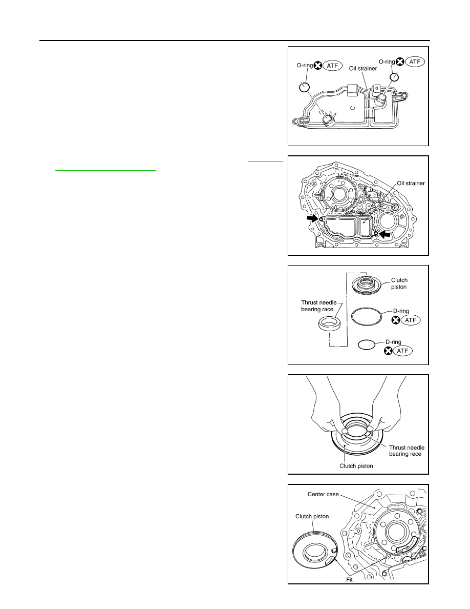
12. Apply ATF to the new O-rings, and install them on the oil

strainer.

CAUTION:

Do not reuse O-rings.

13. Install the oil strainer to the control valve assembly.

14. Tighten the bolts to the specified torque. Refer to 

DLN-154,

"Component Parts Location"

.

15. Apply ATF to the new D-rings, and install them to the clutch pis-

ton.

CAUTION:

Do not reuse D-rings.

16. Install the thrust needle bearing race to the clutch piston.

17. Install the clutch piston to the center case as shown.

CAUTION:

Install so the fitting protrusion of clutch piston aligns with

the dent of center case.

SDIA2782E

SDIA2119E

SDIA2781E

SDIA2189E

SDIA2190E

2011 Pathfinder

TRANSFER ASSEMBLY

DLN-179

< UNIT DISASSEMBLY AND ASSEMBLY >

[TRANSFER: ATX14B]

C

E

F

G

H

I

J

K

L

M

A

B

DLN

N

O

P

18. Remove all the sealant from the oil pressure check port and

inside the center case.

CAUTION:

Remove old sealant adhering to mating surfaces. Also

remove any moisture, oil, or foreign material adhering to

application and mating surfaces.

19. Thread the new oil pressure check plug in 1 or 2 pitches and

apply sealant to the oil pressure check plug threads. Tighten to

the specified torque. Refer to 

DLN-154, "Component Parts

Location"

.

Use Genuine Silicone RTV or equivalent. Refer to 

GI-14,

"Recommended Chemical Products and Sealants"

.

CAUTION:

Do not reuse oil pressure check plug.

20. Install the new snap ring to the clutch hub using suitable tool.

CAUTION:

Do not reuse snap ring.

21. Apply petroleum jelly to the needle bearing, and install the nee-

dle bearing, spacer, clutch drum and clutch hub to the main-

shaft.

22. Install the new snap ring to the mainshaft.

CAUTION:

Do not reuse snap rings.

SDIA3188E

WDIA0101E

WDIA0129E

SDIA2192E

2011 Pathfinder

DLN-180

< UNIT DISASSEMBLY AND ASSEMBLY >

[TRANSFER: ATX14B]

TRANSFER ASSEMBLY

23. Apply ATF each plate, then install them into the clutch drum as

shown.

24. Install the return spring assembly into the clutch hub.

25. Install the press flange by aligning the notches to the clutch hub

as shown.

26. Press the press flange to install the new snap ring into snap ring

groove on mainshaft using Tools.

CAUTION:

Do not reuse snap ring.

27. Install the new snap ring to the mainshaft using suitable tool.

CAUTION:

Do not reuse snap ring.

SDIA2193E

SMT911C

SDIA2194E

Tool number

A: ST22452000 (J-34335)
B: ST30911000 ( — )
C: KV31103300 ( — )

SDIA2111E

SDIA2112E

2011 Pathfinder

TRANSFER ASSEMBLY

DLN-181

< UNIT DISASSEMBLY AND ASSEMBLY >

[TRANSFER: ATX14B]

C

E

F

G

H

I

J

K

L

M

A

B

DLN

N

O

P

28. Apply ATF to the thrust needle bearing and install it on the press

flange.

29. Install the new snap ring to the main shaft.

CAUTION:

Do not reuse snap ring.

30. Install the mainshaft rear bearing to the center case using Tool.

31. Install the mainshaft assembly using a press.

• Press the mainshaft into the center case using Tools.

32. Install the C-rings to the mainshaft.

SDIA2109E

SDIA2195E

Tool number

: ST15310000 (J-25640-B)

SDIA2196E

Tool number

A: ST30911000 ( — )
B: ST35300000 ( — )

SDIA2197E

SDIA2201E

2011 Pathfinder

DLN-182

< UNIT DISASSEMBLY AND ASSEMBLY >

[TRANSFER: ATX14B]

TRANSFER ASSEMBLY

33. Set the washer holder on the mainshaft, and secure it with a

new snap ring.

CAUTION:

Do not reuse snap ring.

34. Apply petroleum jelly to the stem bleeder and install it to the cen-

ter case.

35. Apply ATF to the new seal ring and install it to the main oil pump

cover.

CAUTION:

Do not reuse seal ring.

36. Install the inner gear and outer gear in the main oil pump hous-

ing. Then, measure the side clearance. Refer to 

DLN-191,

"Inspection and Adjustment"

.

37. Install the main oil pump housing, outer gear and inner gear to

the center case.

SDIA2104E

SDIA2780E

SDIA2783E

SDIA2174E

SDIA2188E

2011 Pathfinder

TRANSFER ASSEMBLY

DLN-183

< UNIT DISASSEMBLY AND ASSEMBLY >

[TRANSFER: ATX14B]

C

E

F

G

H

I

J

K

L

M

A

B

DLN

N

O

P

38. Install the main oil pump cover to the center case, and tighten to

the specified torque. Refer to 

DLN-154, "Component Parts

Location"

.

39. Remove all the sealant from the switch location area and inside

the center case.

CAUTION:

Remove old sealant adhering to mounting surfaces. Also

remove any moisture, oil, or foreign material adhering to

application and mounting surfaces.

40. Thread the ATP switch and neutral-4LO switch in one to two

pitches and apply sealant to the threads of the switches. Tighten

to the specified torque. Refer to 

DLN-154, "Component Parts

Location"

.

Use Genuine Silicone RTV or equivalent. Refer to 

GI-14,

"Recommended Chemical Products and Sealants"

.

NOTE:

• Neutral-4LO switch harness connector is gray.

• ATP switch harness connector is black.

41. Install the front drive shaft rear bearing using Tools.

42. Install the front drive shaft to the front bearing using Tools.

SDIA2130E

Tool number

A: KV40100621 (J-25273)
B: ST30032000 (J-26010-01)

SDIA3435E

SDIA2198E

Tool number

A: KV40100621 (J-25273)
B: ST30032000 (J-26010-01)

SDIA2199E

2011 Pathfinder

DLN-184

< UNIT DISASSEMBLY AND ASSEMBLY >

[TRANSFER: ATX14B]

TRANSFER ASSEMBLY

43. Install the drive chain to the front drive shaft and clutch drum.

CAUTION:

Install drive chain by aligning identification marks to the

rear as shown.

44. Tap the front drive shaft while keeping it upright and press-fit the

front drive shaft rear bearing.

CAUTION:

 Do not tap drive chain.

45. Install the front case assembly. 
46. Install the rear case assembly.

Front Case

1. Install the carrier bearing to the sun gear using Tools.

2. Install the new snap ring to the sun gear assembly using suitable

tool.

CAUTION:

Do not reuse snap ring.

3. Apply ATF to the circumference of the new metal bushing and

install it to the sun gear assembly using suitable tool.

CAUTION:

• Do not reuse metal bushing.

• Apply ATF to metal bushing before installing.

SDIA2200E

SMT988C

Tool number

A: ST30911000 ( — )
B: KV31103300 ( — )

SDIA2179E

SDIA2148E

Dimension A

: 7.7 - 8.3 mm (0.303 - 0.327 in)

SDIA3189E

2011 Pathfinder

TRANSFER ASSEMBLY

DLN-185

< UNIT DISASSEMBLY AND ASSEMBLY >

[TRANSFER: ATX14B]

C

E

F

G

H

I

J

K

L

M

A

B

DLN

N

O

P

4. Apply ATF to the new needle bearing and install it to the sun

gear assembly using Tool.

CAUTION:

• Do not reuse needle bearing.

• Apply ATF to needle bearing before installing.

5. Install the sun gear assembly to the planetary carrier assembly.

6. Install the new snap ring to the planetary carrier assembly.

CAUTION:

Do not reuse snap ring.

7. Set the input bearing into the front case and install using Tool.

8. Install the new snap ring into the front case.

CAUTION:

Do not reuse snap ring.

Tool number

: ST33220000 ( — )

Dimension B

: 62.5 - 63.1 mm (2.461 - 2.484 in)

SDIA3190E

SDIA2180E

SDIA2794E

Tool number

: ST30720000 (J-25405)

SDIA2172E

SDIA2171E

2011 Pathfinder


Content      ..     203      204      205      206     ..