Nissan Pathfinder (2011 year). Manual - part 169


  Index      Manuals     Nissan Pathfinder (2011 year) - Service and Repair Manual


Search            copyright infringement  


Content      ..     167      168      169      170     ..


Nissan Pathfinder (2011 year). Manual - part 169


DLK-218

< SYSTEM DESCRIPTION >

[WITHOUT INTELLIGENT KEY SYSTEM]

DOOR LOCK FUNCTION

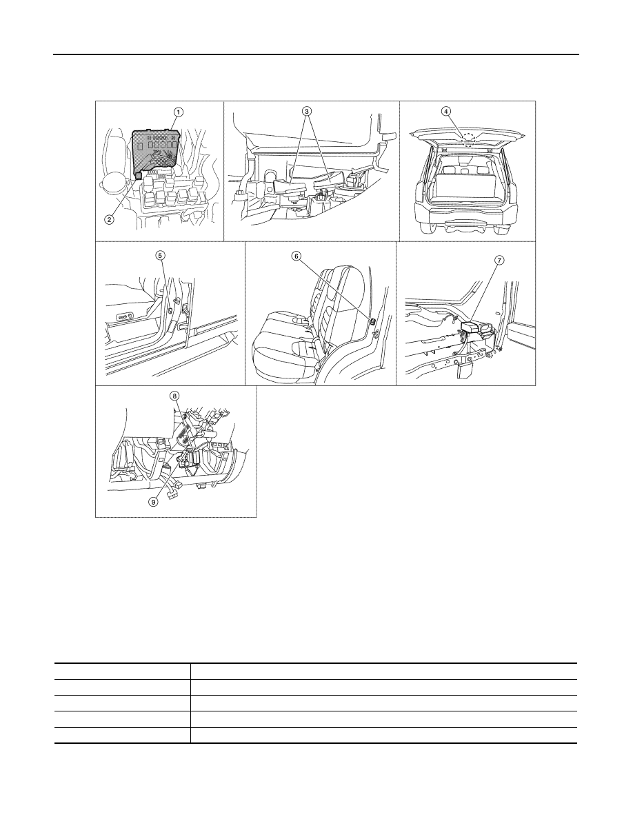
REMOTE KEYLESS ENTRY : Component Parts Location

INFOID:0000000006245595

REMOTE KEYLESS ENTRY : Component Description

INFOID:0000000006245596

1. IPDM E/R E122, E124

2. Horn relay H-1

(view with cover removed)

3. Horn E3 (behind front combination 

lamp LH)

4. Back door cinching latch unit (door ajar 

switch) D502

5. Front door switch LH B8

RH B108

6. Rear door switch LH B18

RH B116

7. Remote keyless entry receiver M120

(view with instrument panel RH re-
moved)

8. BCM M18, M19, M20

(view with instrument panel LH removed)

9. Key switch M27

ALKIA1172ZZ

Item

Function

BCM

Controls the door lock function and room lamp function.

Door lock and unlock switch

Transmits lock or unlock signal to BCM.

Door switch

Transmits door open/close condition to BCM.

Remote keyless entry receiver

Receives lock/unlock signal from the keyfob, and then transmits to BCM.

2011 Pathfinder

HOMELINK UNIVERSAL TRANSCEIVER

DLK-219

< SYSTEM DESCRIPTION >

[WITHOUT INTELLIGENT KEY SYSTEM]

C

D

E

F

G

H

I

J

L

M

A

B

DLK

N

O

P

HOMELINK UNIVERSAL TRANSCEIVER

Component Description

INFOID:0000000006245597

Item

Function

Reference page

Homelink universal transceiver

A maximum of 3 radio signals can be stored and transmitted to operate 
the garage door, etc.

Refer to Owner's 

Manual

2011 Pathfinder

DLK-220

< SYSTEM DESCRIPTION >

[WITHOUT INTELLIGENT KEY SYSTEM]

DIAGNOSIS SYSTEM (BCM)

DIAGNOSIS SYSTEM (BCM)

COMMON ITEM
COMMON ITEM : CONSULT-III Function (BCM - COMMON ITEM)

INFOID:0000000006709537

APPLICATION ITEM

CONSULT-III performs the following functions via CAN communication with BCM.

SYSTEM APPLICATION

BCM can perform the following functions.

Direct Diagnostic Mode

Description

Ecu Identification

The BCM part number is displayed.

Self Diagnostic Result

The BCM self diagnostic results are displayed.

Data Monitor

The BCM input/output data is displayed in real time.

Active Test

The BCM activates outputs to test components.

Work support

The settings for BCM functions can be changed.

Configuration

• The vehicle specification can be read and saved.
• The vehicle specification can be written when replacing BCM.

CAN Diag Support Mntr

The result of transmit/receive diagnosis of CAN communication is displayed.

System

Sub System

Direct Diagnostic Mode

E

cu

 Id

en

tifi

ca

tio

n

Se

lf Di

ag

no

st

ic Re

su

lt

Da

ta

 Mo

ni

tor

A

cti

ve

 T

est

W

o

rk support

Co

nf

igu

rat

ion

CA

N Diag

 Su

pp

ort Mn

tr

Door lock

DOOR LOCK

×

×

×

×

Rear window defogger

REAR DEFOGGER

×

×

Warning chime

BUZZER

×

×

Interior room lamp timer

INT LAMP

×

×

×

Remote keyless entry system

MULTI REMOTE ENT

×

×

×

Exterior lamp

HEAD LAMP

×

×

×

Wiper and washer

WIPER

×

×

×

Turn signal and hazard warning lamps FLASHER

×

×

Air conditioner

AIR CONDITIONER

×

Intelligent Key system

INTELLIGENT KEY

×

Combination switch

COMB SW

×

BCM

BCM

×

×

×

×

×

Immobilizer

IMMU

×

×

×

Interior room lamp battery saver

BATTERY SAVER

×

×

×

Back door open

TRUNK

×

×

Vehicle security system

THEFT ALM

×

×

×

RAP system

RETAINED PWR

×

×

×

Signal buffer system

SIGNAL BUFFER

×

×

TPMS

AIR PRESSURE MONITOR

×

×

×

×

Panic alarm system

PANIC ALARM

×

2011 Pathfinder

DIAGNOSIS SYSTEM (BCM)

DLK-221

< SYSTEM DESCRIPTION >

[WITHOUT INTELLIGENT KEY SYSTEM]

C

D

E

F

G

H

I

J

L

M

A

B

DLK

N

O

P

DOOR LOCK
DOOR LOCK : CONSULT-III Function (BCM - DOOR LOCK)

INFOID:0000000006709538

SELF DIAGNOSTIC RESULT

Refer to 

BCS-46, "DTC Index"

.

DATA MONITOR

* : with Intelligent Key
** : without Intelligent Key

ACTIVE TEST

WORK SUPPORT

Monitor Item [Unit]

Description

IGN ON SW [On/Off]

Indicates condition of ignition switch ON position.

KEY ON SW [On/Off]

Indicates condition of key switch.

CDL LOCK SW [On/Off]

Indicates condition of lock signal from door lock and unlock switch.

CDL UNLOCK SW [On/Off]

Indicates condition of unlock signal from door lock and unlock switch.

DOOR SW-DR [On/Off]

Indicates condition of front door switch LH.

DOOR SW-AS [On/Off]

Indicates condition of front door switch RH.

DOOR SW-RR [On/Off]

Indicates condition of rear door switch RH.

DOOR SW-RL [On/Off]

Indicates condition of rear door switch LH.

BACK DOOR SW [On/Off]

Indicates condition of back door switch.

KEY CYL LK-SW [On/Off]

Indicates condition of lock signal from door key cylinder switch.

KEY CYL UN-SW [On/Off]

Indicates condition of unlock signal from door key cylinder switch.

I-KEY LOCK* [On/Off]

Indicates condition of lock signal from Intelligent Key.

I-KEY UNLOCK* [On/Off]

Indicates condition of unlock signal from Intelligent Key.

KEYLESS LOCK** [On/Off]

Indicates condition of lock signal from keyfob.

KEYLESS UNLOCK** [On/Off]

Indicates condition of unlock signal from keyfob.

Test Item

Description

DOOR LOCK

This test is able to check door lock operation [OTR ULK/DR UNLK/ALL ULK/ALL LCK].

Support Item

Setting

Description

DOOR LOCK-UNLOCK SET

On*

Automatic door locks function ON.

Off

Automatic door locks function OFF.

ANTI-LOCK OUT SET

Off

Anti lock out function OFF.

On*

Anti lock out function ON.

AUTOMATIC DOOR LOCK SELECT

SHIFT OUT 
OF PARK

Doors lock automatically when shifted out of park (P).

VH SPD*

Doors lock automatically when vehicle speed reaches 24 km/h (15 mph).

AUTOMATIC DOOR UNLOCK
SELECT

MODE6

Drivers door unlocks automatically when key is removed.

MODE5

Drivers door unlocks automatically when shifted into park (P).

MODE4

Drivers door unlocks automatically when ignition is switched from ON to OFF.

MODE3

Doors unlock automatically when key is removed.

MODE2

Doors unlock automatically when shifted into park (P).

MODE1*

Doors unlock automatically when ignition is switched from ON to OFF.

2011 Pathfinder

DLK-222

< SYSTEM DESCRIPTION >

[WITHOUT INTELLIGENT KEY SYSTEM]

DIAGNOSIS SYSTEM (BCM)

* : Initial setting

MULTI REMOTE ENT
MULTI REMOTE ENT : CONSULT-III Function (BCM - MULTI REMOTE ENT)

INFOID:0000000006709539

DATA MONITOR

ACTIVE TEST

WORK SUPPORT

AUTOMATIC LOCK/UNLOCK
SELECT

On*

Automatic lock/unlock function ON.

Off

Automatic lock/unlock function OFF.

Support Item

Setting

Description

Monitor Item [Unit]

Description

IGN ON SW [On/Off]

Indicates condition of ignition switch ON position.

KEY ON SW [On/Off]

Indicates condition of key switch.

ACC ON SW [On/Off]

Indicates condition of ignition switch ACC position.

KEYLESS LOCK [On/Off]

Indicates condition of lock signal from keyfob.

KEYLESS UNLOCK [On/Off]

Indicates condition of unlock signal from keyfob.

KEYLESS PANIC [On/Off]

Indicates condition of panic signal from keyfob.

DOOR SW-DR [On/Off]

Indicates condition of front door switch LH.

DOOR SW-AS [On/Off]

Indicates condition of front door switch RH.

DOOR SW-RR [On/Off]

Indicates condition of rear door switch RH.

DOOR SW-RL [On/Off]

Indicates condition of rear door switch LH.

CDL LOCK SW [On/Off]

Indicates condition of lock signal from door lock and unlock switch.

CDL UNLOCK SW [On/Off]

Indicates condition of unlock signal from door lock and unlock switch.

KEY CYL LK SW [On/Off]

Indicates condition of lock signal from door key cylinder switch.

Test Item

Description

DOOR LOCK

This test is able to check door lock operation [OTR ULK/DR UNLK/ALL ULK/ALL LCK].

PW REMOTO DOWN SET

This test is able to check keyfob  power window down operation [Off/On].

FLASHER

This test is able to check hazard reminder operation [Off/LH/RH].

HORN

This test is able to check horn operation [On].

Support Item

Setting

Description

HORN CHIRP SET

Off

Horn chirp function can be changed in this mode.

On*

HAZARD LAMP SET

MODE4*

Lock and Unlock

Hazard warning lamp function can be changed in this mode.

MODE3

Lock Only

MODE2

Unlock Only

MODE1

OFF

MULTI ANSWER BACK SET

MODE2

Lock

Hazard warning lamps flash twice and horn does not sound.

Unlock

Hazard warning lamps do not flash and horn does not sound.

MODE1*

Lock

Hazard warning lamps flash twice and horn sounds once.

Unlock

Hazard warning lamps flash once and horn does not sound.

2011 Pathfinder

DIAGNOSIS SYSTEM (BCM)

DLK-223

< SYSTEM DESCRIPTION >

[WITHOUT INTELLIGENT KEY SYSTEM]

C

D

E

F

G

H

I

J

L

M

A

B

DLK

N

O

P

*: Initial setting

TRUNK
TRUNK : CONSULT-III Function (BCM - TRUNK)

INFOID:0000000006709541

DATA MONITOR

ACTIVE TEST

AUTO LOCK SET

MODE3

1 min

Auto locking function can be changed in this mode.

MODE2

OFF

MODE1* 5 min

PANIC ALRM SET

MODE3

1.5 sec

Panic alarm operation can be changed in this mode.

MODE2

OFF

MODE1* 0.5 sec

PW DOWN SET

MODE3

5 sec

Keyfob power window down can be changed in this mode.

MODE2

OFF

MODE1* 3 sec

REMO CONT ID REGIST

Keyfob ID code can be registered.

REMO CONT ID ERASUR

Keyfob ID code can be erased.

REMO CONT ID CONFIR

Keyfob ID code registration is displayed.

Support Item

Setting

Description

Monitor Item [Unit]

Description

IGN ON SW [On/Off]

Indicates condition of ignition switch ON position.

TRNK OPNR SW [On/Off]

Indicates condition of back door opener switch.

VEHICLE SPEED [km/h/mph]

Indicates vehicle speed signal received from combination meter on CAN communication 
line.

Test item

Description

TRUNK/BACK DOOR

This test is able to check back door latch operation [Open].

2011 Pathfinder

DLK-224

< DTC/CIRCUIT DIAGNOSIS >

[WITHOUT INTELLIGENT KEY SYSTEM]

U1000 CAN COMM CIRCUIT

DTC/CIRCUIT DIAGNOSIS

U1000 CAN COMM CIRCUIT

Description

INFOID:0000000006245602

CAN (Controller Area Network) is a serial communication line for real time applications. It is an on-vehicle mul-

tiplex communication line with high data communication speed and excellent error detection ability. Modern

vehicle is equipped with many electronic control unit, and each control unit shares information and links with

other control units during operation (not independent). In CAN communication, control units are connected

with 2 communication lines (CAN H-line, CAN L-line) allowing a high rate of information transmission with less

wiring. Each control unit transmits/receives data but selectively reads required data only.

CAN Communication Signal Chart. Refer to 

LAN-53, "CAN Communication Signal Chart"

.

DTC Logic

INFOID:0000000006245603

DTC DETECTION LOGIC

Diagnosis Procedure

INFOID:0000000006245604

1.

PERFORM SELF DIAGNOSTIC

1. Turn ignition switch ON and wait for 2 second or more.

2. Check “Self Diagnostic Result”.
Is “CAN COMM CIRCUIT” displayed?

YES

>> Refer to 

LAN-14, "Trouble Diagnosis Flow Chart"

.

NO

>> Refer to 

GI-37, "Intermittent Incident"

.

DTC

CONSULT-III display 

description

DTC Detection Condition

Possible cause

U1000

CAN COMM CIRCUIT

When BCM cannot communicate CAN com-
munication signal continuously for 2 sec-
onds or more.

In CAN communication system, any item (or items) 
of the following listed below is malfunctioning.
• Transmission
• Receiving (ECM)
• Receiving (VDC/TCS/ABS)
• Receiving (METER/M&A)
• Receiving (TCM)

2011 Pathfinder

U1010 CONTROL UNIT (CAN)

DLK-225

< DTC/CIRCUIT DIAGNOSIS >

[WITHOUT INTELLIGENT KEY SYSTEM]

C

D

E

F

G

H

I

J

L

M

A

B

DLK

N

O

P

U1010 CONTROL UNIT (CAN)

DTC Logic

INFOID:0000000006245605

DTC DETECTION LOGIC

Diagnosis Procedure

INFOID:0000000006245606

1.

REPLACE BCM

When DTC [U1010] is detected, replace BCM. Refer to 

BCS-55, "Removal and Installation"

.

>> Replace BCM.

Special Repair Requirement

INFOID:0000000006245607

1.

REQUIRED WORK WHEN REPLACING BCM

The BCM must be initialized when replaced. Refer to 

BCS-55, "Removal and Installation"

 for BCM configura-

tion.

Initialize NVIS by CONSULT-III. For the details of initialization refer to CONSULT-III Operation Manual.

>> Work End.

DTC

CONSULT-III display de-

scription

DTC Detection Condition

Possible cause

U1010

CONTROL UNIT (CAN)

BCM detected internal CAN communication circuit malfunction.

BCM

2011 Pathfinder


Content      ..     167      168      169      170     ..