Nissan Pathfinder (2010 year). Manual - part 589
SR-10
< ON-VEHICLE REPAIR >
FRONT PASSENGER AIR BAG MODULE
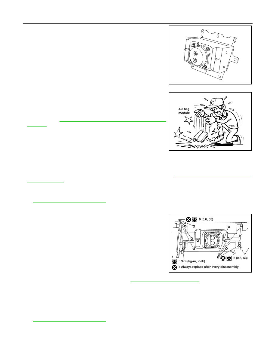
• When servicing the SRS, do not work from directly in front of
air bag module.
• Always place front passenger air bag module with caution
label side facing upward.
• Do not insert any foreign objects (screwdriver, etc.) into air
bag module or harness connectors.
• Do not disassemble air bag module.
• Do not use old nuts after removal; replace with new nuts.
• Do not expose the front passenger air bag module to tempera-
tures exceeding 90
°
C (194
°
F).
• Replace the air bag module if it has been dropped or sus-
tained an impact.
• Do not allow oil, grease or water to come in contact with the
air bag module.
• For removal/installation of the direct-connect SRS connec-
tors, refer to
SRC-9, "Direct-connect SRS Component Con-
.
INSTALLATION
Original Passenger Air Bag Module
Installation is in the reverse order of removal.
• For removal/installation of the direct-connect SRS connectors, refer to
SRC-9, "Direct-connect SRS Compo-
CAUTION:
• Always work from the side of or under front passenger air bag module.
• After the work is completed, perform self-diagnosis to check that no malfunction is detected. Refer
Service Replacement Passenger Air Bag Module
1. Install the front passenger air bag module to the instrument
panel pad assembly.
2. Install the instrument panel assembly. Refer to
IP-12, "Removal and Installation"
3. Connect the front passenger air bag module harness connector to yellow 4-pin service replacement air
bag connector and fasten connector to mounting bracket.
CAUTION:
• Always work from the side of or under front passenger air bag module.
• After the work is completed, perform self-diagnosis to check that no malfunction is detected. Refer
WIRING HARNESS MODIFICATION
The passenger air bag module originally installed in the vehicle uses direct-connect style harness connectors.
Service replacement passenger air bag modules use tab-locking style harness connectors. If the passenger
WHIA0111E
SBF814E
WHIA0269E
2010 Pathfinder