Nissan Pathfinder (2010 year). Manual - part 555


  Index      Manuals     Nissan Pathfinder (2010 year) - Service and Repair Manual


Search            copyright infringement  


Content      ..     553      554      555      556     ..


Nissan Pathfinder (2010 year). Manual - part 555


RSU-18

< REMOVAL AND INSTALLATION >

STABILIZER BAR

STABILIZER BAR

Removal and Installation

INFOID:0000000005260318

REMOVAL

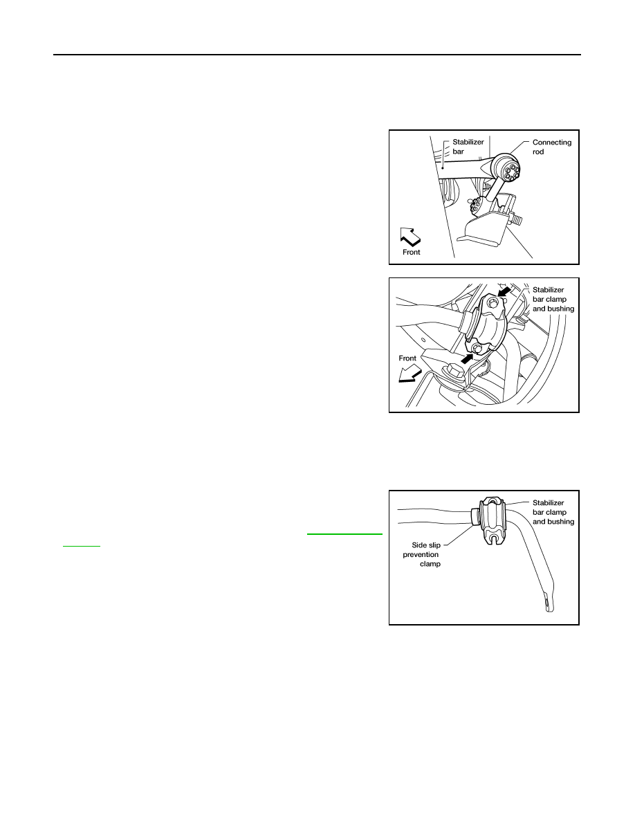
1. Disconnect the stabilizer bar ends from the connecting rods

using power tool.

2. Remove the stabilizer bar clamps using power tool, and remove

the stabilizer bar bushings.

3. Remove the stabilizer bar.

INSPECTION AFTER REMOVAL

• Check stabilizer bar for any deformation, cracks, or damage and replace if necessary.

• Check rubber bushings for deterioration, or cracks and replace if necessary.

INSTALLATION

Installation is in the reverse order of removal.

• Install the stabilizer bar bushings and clamps so they are posi-

tioned outside of the sideslip prevention clamp on the stabilizer

bar.

• Tighten the nuts and bolts to specification. Refer to 

RSU-10, "Com-

ponent"

.

LEIA0111E

LEIA0113E

LEIA0112E

2010 Pathfinder

REAR SUSPENSION MEMBER

RSU-19

< REMOVAL AND INSTALLATION >

C

D

F

G

H

I

J

K

L

M

A

B

RSU

N

O

P

REAR SUSPENSION MEMBER

Removal and Installation

INFOID:0000000005260313

COMPONENTS

REMOVAL

1. Remove both of the rear wheel and tire assemblies using power tool.
2. Remove the spare tire.

1.

Seat belt latch anchor

2.

Stabilizer bar bushing

3.

Stabilizer bar clamp

4.

Stabilizer bar

5.

Connecting rod

6.

Front lower link

7.

Knuckle

8.

Bushing

9.

Rear lower link

10. Shock absorber

11. Suspension arm

12. Lower rubber seat

13. Coil spring

14. Upper rubber seat

15. Rear suspension member

16. Spare tire bracket

17. Bound bumper

AWEIA0022GB

2010 Pathfinder

RSU-20

< REMOVAL AND INSTALLATION >

REAR SUSPENSION MEMBER

3. Remove the brake caliper without disconnecting the brake hoses, using power tool. Reposition the brake

caliper out of the way using a suitable wire. Refer to 

BR-45, "Removal and Installation of Brake Caliper

and Disc Rotor"

.

CAUTION:

• Do not crimp or stretch the brake hose when repositioning the brake caliper out of the way.

• Do not press the brake pedal while the brake caliper is positioned out of the way.

4. Remove the two rear brake rotors.
5. Remove the two rear drive shafts. Refer to 

RAX-8, "Removal and Installation"

.

6. Disconnect the parking brake cables brackets from the rear suspension member.
7. Disconnect the two rear wheel sensor connectors and harness clips.
8. Remove the rear final drive vent tube from the rear suspension member and frame.
9. Remove the rear final drive. Refer to 

DLN-422, "Removal and Installation"

 (R200), 

DLN-460, "Removal

and Installation"

 (R230).

10. Set a suitable jack to support each of the rear lower links and the

coil spring tension.

11. Remove both of the rear lower link outer bolts using power tool,

and lower the jack to remove the rear coil springs, and the upper

and lower rubber seats.

12. Remove the two bolts to disconnect the seat belt latch anchor

from the rear suspension member using power tool.

13. Disconnect both of the connecting rods from the rear stabilizer

bar.

LEIA0077E

LEIA0109E

LEIA0111E

2010 Pathfinder

REAR SUSPENSION MEMBER

RSU-21

< REMOVAL AND INSTALLATION >

C

D

F

G

H

I

J

K

L

M

A

B

RSU

N

O

P

14. Set a suitable jack under each front lower link for support and

remove the shock absorber upper end bolts and lower end bolts

using power tool.

15. Remove both of the shock absorbers.

16. Set a suitable jack under the rear suspension member.
17. Remove the six rear suspension member bolts using power tool.
18. Slowly lower the jack supporting the rear suspension member to

access the fuel filler tube bracket, then remove the two bolts to

disconnect the fuel filler tube bracket from the rear suspension

member. 

19. Slowly lower the jack to remove the rear suspension member, suspension arm, front and rear lower links,

knuckles, and stabilizer bar as an assembly.

20. Remove the suspension arm, spare tire bracket, stabilizer bar, front and rear lower links, and the knuckles

from the rear suspension member using power tool.

INSPECTION AFTER REMOVAL

Check rear suspension member for deformation, cracks, and other damage and replace if necessary.

INSTALLATION

Installation is in the reverse order of removal.

• When raising the rear suspension member assembly, use the

locating pins to align the rear suspension member to the vehicle

body.

LEIA0110E

LEIA0114E

LEIA0083E

2010 Pathfinder

RSU-22

< REMOVAL AND INSTALLATION >

REAR SUSPENSION MEMBER

• When installing the upper and lower rubber seats for the rear coil

springs, the arrow embossed on the rubber seats must point out

toward the wheel and tire assembly.

• Perform final tightening of the nuts and bolts for the links (with rubber bushings) under unladen conditions

with the tires on level ground.

• Adjust the parking brake cables. Refer to 

PB-5, "On-Vehicle Service"

.

• Check the wheel alignment. Refer to 

FSU-6, "Front Wheel Alignment"

.

LEIA0076E

2010 Pathfinder

SERVICE DATA AND SPECIFICATIONS (SDS)

RSU-23

< SERVICE DATA AND SPECIFICATIONS (SDS) 

C

D

F

G

H

I

J

K

L

M

A

B

RSU

N

O

P

SERVICE DATA AND SPECIFICATIONS (SDS)

SERVICE DATA AND SPECIFICATIONS (SDS)

Wheel Alignment (Unladen*)

INFOID:0000000005260319

*1: Fuel, radiator coolant and engine oil full. Spare tire, jack, hand tools and mats in designed positions. 

Camber
Degree minute (decimal degree)

Minimum

- 0

°

 32

 (- 0.53

°

)

Nominal

- 0

°

 2

 (- 0.03

°

)

Maximum

0

°

 28

 (0.47

°

)

Total toe-in

Distance difference between right and 
left side (AR-BR)-(AL-BL)

 :Front 

Minimum

-2 mm (-0.08 in)

Nominal

0 mm (0 in)

Maximum

2 mm (0.08 in)

Distance [left side (AL-BL) or right 
side (AR-BR)] from center line of body

Minimum

- 1.4 mm (- 0.055 in)

Nominal

1.9 mm (0.075 in)

Maximum

5.2 mm (0.205 in)

Angle (left side or right side)
Degree minute (decimal degree)

Minimum

- 0

°

 3' (-0.05

°

)

Nominal

0

°

 4' (0.07

°

)

Maximum

0

°

 11' (0.18

°

)

ALEIA0059ZZ

2010 Pathfinder

RSU-24

< SERVICE DATA AND SPECIFICATIONS (SDS) 

SERVICE DATA AND SPECIFICATIONS (SDS)

Ball Joint

INFOID:0000000005260320

*: Measurement point is at the bolt groove of the ball stud.

Wheelarch Height (Unladen*)

INFOID:0000000005260321

Unit: mm (in)

*1: Fuel, radiator coolant and engine oil full. Spare tire, jack, hand tools and mats in designated positions.

Ball joint position

Upper

Lower

Swinging force* (A)

11.4 - 145.5 N (1.16 - 14.8 kg, 2.56 - 32.7 lb)

11.0 - 140.7 N (1.12 - 14.35 kg, 2.47 - 31.63 lb)

Turning torque (B)

0.5 - 6.4 N·m (0.06 - 0.65 kg-m, 5 - 56 in-lb)

0.5 - 6.4 N·m (0.06 - 0.65 kg-m, 5 - 56 in-lb)

Vertical end play (C)

0 mm (0 in)

0 mm (0 in)

Height (D)

44 mm (1.73 in)

45.5 mm (1.79 in)

WEIA0131E

Engine

VQ40DE

VK56DE

Drive type

2WD

4WD

4WD

Tire size

P245/75R16

P265/65R17

P265/60R18

P245/75R16

P265/65R17 P265/60R18 P265/60R18

Front wheelarch height 
(Hf)

867

(34.13)

865 

(34.06)

875

(34.45)

874

(34.41)

876 (34.49)

Rear wheelarch height 
(Hr)

875

(34.45)

873

(34.37)

884

(34.80)

883

(34.76)

886 (34.88)

LEIA0085E

2010 Pathfinder


Content      ..     553      554      555      556     ..