Nissan Pathfinder (2010 year). Manual - part 552


  Index      Manuals     Nissan Pathfinder (2010 year) - Service and Repair Manual


Search            copyright infringement  


Content      ..     550      551      552      553     ..


Nissan Pathfinder (2010 year). Manual - part 552


RF-50

< PREPARATION >

PREPARATION

PREPARATION

PREPARATION

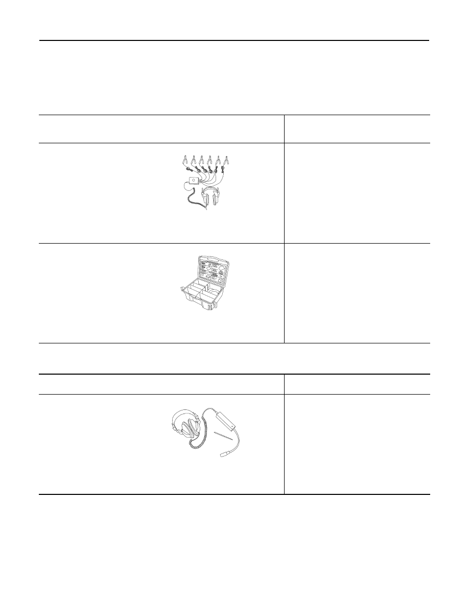
Special Service Tool

INFOID:0000000005255260

The actual shapes of Kent-Moore tools may differ from those of special service tools illustrated here.

Commercial Service Tool

INFOID:0000000005255261

Tool number
(Kent-Moore No.)
Tool name

Description

(J-39570)
Chassis ear

Locating the noise

(J-43980)
NISSAN Squeak and
Rattle Kit

Repairing the cause of noise

SIIA0993E

SIIA0994E

(Kent-Moore No.)
Tool name

Description

(J-39565)
Engine ear

Locating the noise

SIIA0995E

2010 Pathfinder

SUNROOF SYSTEM

RF-51

< ON-VEHICLE REPAIR >

C

D

E

F

G

H

I

J

L

M

A

B

RF

N

O

P

ON-VEHICLE REPAIR

SUNROOF SYSTEM

Adjustment

INFOID:0000000005255262

Inspect then measure the gap and height difference between the glass lid assembly and roof panel; compare

to specifications. Determine which procedure to follow based on results of measurements. 

GAP ADJUSTMENT 

If a gap or minor height difference between glass lid assembly and roof panel is found, adjust in the following

manner:
1. Open sunshade assembly and tilt glass lid assembly up.
2. Loosen glass lid assembly screws (2 each on left and right sides), then tilt glass lid assembly down.
3. Manually adjust glass lid assembly from outside of vehicle so it is within specification "A-A" as shown.
4. After adjustment, tilt glass lid assembly up and tighten screws.
5. Tilt glass lid assembly up and down several times to check that it moves and seals properly.

HEIGHT DIFFERENCE ADJUSTMENT

If an excessive height difference between glass lid assembly and roof panel is found, adjust in the following

manner:
1. Remove headlining. Refer to 

INT-19, "Removal and Installation"

.

2. Loosen sunroof frame assembly nuts and sunroof bracket bolts.
3. Add shims until gap is within specification "A-A" as shown.

NOTE:

Temporarily snug nuts and bolts to prevent movement between each adjustment.

4. Tilt glass lid assembly up and down several times to check that it moves and seals properly.
5. Tighten sunroof frame assembly nuts and sunroof bracket bolts. 

NOTE:

A.

0.8 

±

 1.5mm (0.03 

±

 0.06 in.)

B.

4.0 

±

 0.7mm (0.16 

±

 0.03 in)

WIIA1071E

2010 Pathfinder

RF-52

< ON-VEHICLE REPAIR >

SUNROOF SYSTEM

First tighten left front then right rear sunroof frame assembly nuts to prevent uneven torque while tighten-

ing remaining sunroof bracket bolts.

6. Install headlining. Refer to 

INT-19, "Removal and Installation"

.

Removal and Installation

INFOID:0000000005255263

ALKIA1850GB

2010 Pathfinder

SUNROOF SYSTEM

RF-53

< ON-VEHICLE REPAIR >

C

D

E

F

G

H

I

J

L

M

A

B

RF

N

O

P

• After any adjustment, check sunroof operation and glass lid alignment.

• Handle glass lid with care so not to cause damage.

• For easier installation, mark each point before removal.

CAUTION:

• Always work with a helper.

• Before removal, fully close the glass lid assembly. Then, after removal, do not move the motor

assembly.

• After installing the sunroof and glass lid, check gap adjustment to ensure there is no malfunction.

SUNROOF UNIT

Removal

CAUTION:

• Always work with a helper.

• When taking sunroof unit out, use shop cloths to protect the seats and trim from damage.

• After installing the sunroof unit and glass lid, be sure to check gap adjustment to ensure there is no

malfunction.

1. Remove headlining. Refer to 

INT-19, "Removal and Installation"

2. Remove the sunroof glass lid.
3. Disconnect sunroof motor and remove the overhead console bracket.
4. Disconnect the drain hoses.
5. Remove front sunroof frame assembly nuts.
6. Remove the rear sunroof bracket bolts. 
7. Remove the side bolts and the sunroof unit.

Installation

1. Position the sunroof frame assembly and install the side bolts.
2. Install the rear sunroof bracket bolts.
3. Install front sunroof frame assembly nuts.
4. Connect the drain hoses.
5. Install the overhead console bracket and connect the sunroof motor.
6. Install the sunroof glass lid.
7. Install headlining. Refer to 

INT-19, "Removal and Installation"

.

GLASS LID

Removal

1. Open sunshade.
2. Ensure glass lid is closed.
3. Remove the screws securing glass lid to the sunroof frame assembly.
4. Remove the glass lid assembly.

Installation

1. Position glass lid to sunroof assembly.

1. Glass lid assembly

2.

Sunroof lid seal

3. Wind deflector

4. Rear drain hoses

5.

Shade stoppers

6. Sunroof bracket

7. Sunroof frame assembly

8.

 Front drain hoses

9. Sunroof motor assembly

10. Sunshade assembly

2010 Pathfinder

RF-54

< ON-VEHICLE REPAIR >

SUNROOF SYSTEM

2. Install the glass lid assembly screws. (First tighten left front bolt,

then tighten right rear bolt on glass lid to prevent lid from moving

while tightening other bolts.) 

3. Adjust the sunroof glass. Refer to 

RF-51, "Adjustment"

.

WIND DEFLECTOR

Removal

1. Open the sunroof.
2. Remove screws from the left, center, and right side wind deflec-

tor holders.

3. Remove the wind deflector from the sunroof frame assembly.

Installation

Installation is in the reverse order of removal.

SUNSHADE

Removal

1. Remove the sunroof frame assembly. Refer to 

RF-52, "Removal and Installation"

.

2. Remove the sunshade stoppers (2 points) from the rear end of

the sunroof frame assembly.

3. Remove the sunshade assembly from the rear end of the sun-

roof frame assembly.

Installation

Installation is in the reverse order of removal.

SUNROOF MOTOR

Removal

CAUTION:

• When removing the sunroof motor, be sure that the sunroof is in the fully closed position.

• Never run the removed motor as a single unit.

1. Position the sunroof assembly in the fully closed position.
2. Remove the front roof console assembly. Refer to 

INT-19, "Removal and Installation"

.

WIIA0252E

WIIA0424E

LIIA1672E

2010 Pathfinder

SUNROOF SYSTEM

RF-55

< ON-VEHICLE REPAIR >

C

D

E

F

G

H

I

J

L

M

A

B

RF

N

O

P

3. Disconnect the harness connector from the sunroof motor

assembly.

4. Remove the mounting screws and the sunroof motor assembly.

Installation

CAUTION:

Before installing the sunroof motor assembly, be sure to place the link and wire assembly in the sym-

metrical and fully closed position.

1. Move the sunroof motor assembly laterally little by little so that

the gear is completely engaged into the wire on the sunroof unit

and the mounting surface becomes parallel. Then secure the

motor with bolts.

2. Connect the harness connector to the sunroof motor assembly.

3. Install the front roof console assembly. Refer to 

INT-19, "Removal and Installation"

.

4. Reset the sunroof motor memory. Refer to 

RF-5, "ADDITIONAL SERVICE WHEN REPLACING CON-

TROL UNIT : Special Repair Requirement"

.

DRAIN HOSES

Removal

LIIA1673E

LIIA1674E

1.

Drain hoses

WIIA1072E

2010 Pathfinder

RF-56

< ON-VEHICLE REPAIR >

SUNROOF SYSTEM

1. Remove the headlining. Refer to 

INT-19, "Removal and Installation"

.

2. Visually check the drain hoses for proper connections, damage or deterioration.
3. Remove each drain hose and check visually for damage, cracks or deterioration.
4. Pour water through the drain hose to check for damage.
• If any damage is found, replace the drain hose.

Installation

Installation is in the reverse order of removal.

WEATHERSTRIP

Visually check weatherstrip for any damage, deterioration, or flattening. 

• In the case of leakage around glass lid, close glass lid and pour water around it to find the damaged or

gaped portion, remove glass lid assembly. Refer to: 

RF-52, "Removal and Installation"

.

• If any damage is found, inspect and repair the body sealing surface, replace sunroof lid seal, or replace

glass lid assembly. Refer to GLASS LID in this section.

CAUTION:

Do not remove weatherstrip.

LINK AND WIRE ASSEMBLY

NOTE:

Before replacing any suspect part, be sure it is the source of the noise.
1. Visually check to determine if a sufficient amount of petroleum jelly has been applied to the wire or rail

groove. If not, add petroleum jelly as required.

2. Check wire for any damage or deterioration. If any damage is found, remove rear guide, then replace

wire.

LIIA0272E

2010 Pathfinder

RSU-1

SUSPENSION

C

D

F

G

H

I

J

K

L

M

SECTION 

RSU

A

B

RSU

N

O

P

CONTENTS

REAR SUSPENSION

PRECAUTION ...............................................

2

PRECAUTIONS ...................................................

2

Precaution for Supplemental Restraint System 
(SRS) "AIR BAG" and "SEAT BELT PRE-TEN-
SIONER" .................................................................
..

2

Precaution Necessary for Steering Wheel Rota-
tion After Battery Disconnect ...................................
..

2

Precaution for Rear Suspension ...............................

3

PREPARATION ............................................

4

PREPARATION ...................................................

4

Commercial Service Tool  ..........................................

4

SYMPTOM DIAGNOSIS  ...............................

5

NOISE, VIBRATION, AND HARSHNESS 
(NVH) TROUBLESHOOTING  .............................

5

NVH Troubleshooting Chart  ......................................

5

ON-VEHICLE MAINTENANCE .....................

6

REAR SUSPENSION ASSEMBLY  .....................

6

On-Vehicle Inspection  ...............................................

6

Wheel Alignment Inspection ......................................

6

SHOCK ABSORBER  ..........................................

9

Inspection ..................................................................

9

ON-VEHICLE REPAIR .................................

10

REAR SUSPENSION ASSEMBLY ...................

10

Component ..............................................................

10

REMOVAL AND INSTALLATION ...............

11

SHOCK ABSORBER  ........................................

11

Removal and Installation  .........................................

11

Disposal ...................................................................

11

SUSPENSION ARM  ..........................................

12

Removal and Installation  .........................................

12

FRONT LOWER LINK .......................................

14

Removal and Installation  .........................................

14

REAR LOWER LINK & COIL SPRING .............

16

Removal and Installation  .........................................

16

STABILIZER BAR .............................................

18

Removal and Installation  .........................................

18

REAR SUSPENSION MEMBER .......................

19

Removal and Installation  .........................................

19

SERVICE DATA AND SPECIFICATIONS 
(SDS) ............................................................

23

SERVICE DATA AND SPECIFICATIONS 
(SDS) .................................................................

23

Wheel Alignment (Unladen*)  ...................................

23

Ball Joint  ..................................................................

24

Wheelarch Height (Unladen*) ..................................

24

2010 Pathfinder


Content      ..     550      551      552      553     ..