Nissan Pathfinder (2010 year). Manual - part 505


  Index      Manuals     Nissan Pathfinder (2010 year) - Service and Repair Manual


Search            copyright infringement  


Content      ..     503      504      505      506     ..


Nissan Pathfinder (2010 year). Manual - part 505


MWI-12

< FUNCTION DIAGNOSIS >

METER SYSTEM

FUEL GAUGE : Component Description

INFOID:0000000005260343

ENGINE OIL PRESSURE GAUGE
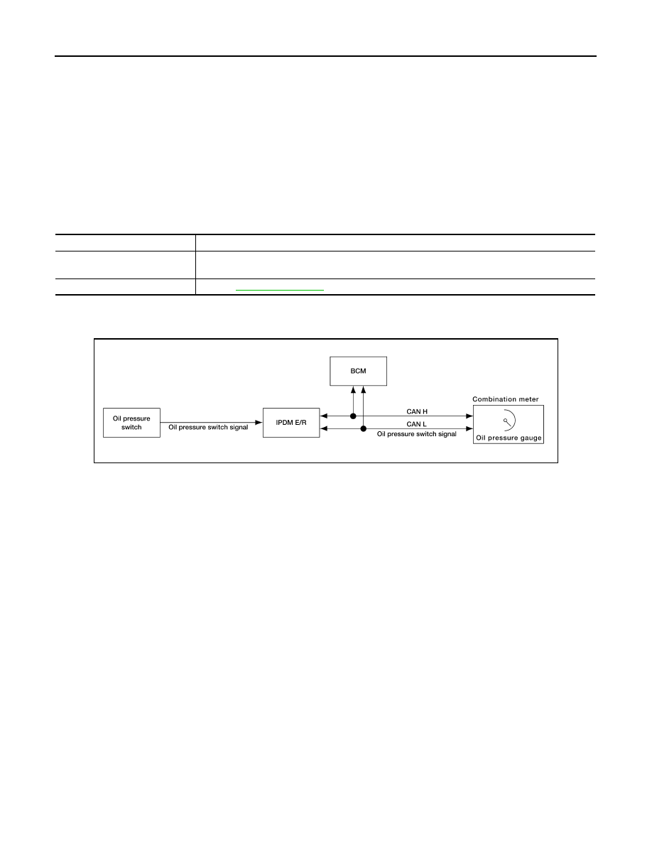
ENGINE OIL PRESSURE GAUGE : System Diagram

INFOID:0000000005260344

ENGINE OIL PRESSURE GAUGE : System Description

INFOID:0000000005260345

The engine oil pressure gauge indicates whether the engine oil pressure is low or normal.

The oil pressure gauge is controlled by the IPDM E/R. The IPDM E/R reads the ON/OFF signals from the oil

pressure switch and transmits the oil pressure switch signal to the combination meter via BCM with the CAN

communication line. The oil pressure gauge displays a low or normal indication according to the oil pressure

switch signal received via CAN communication.

1.

Combination meter M24

2.

Fuel level sensor unit and fuel pump C5 
(view with fuel tank removed)

3.

ECM (view with ECM cover removed)
E7 (with VK56DE)
E16 (with VQ40DE)
A. Coolant reservoir

4.

ABS actuator and electric unit (control 
unit)
E125 (with VQ40DE)
E127 (with VK56DE)

5.

Oil pressure switch E208 (with VQ40DE)
A. Oil pan (upper)

6.

Oil pressure switch F4 (with VK56DE)
A: Oil pan (upper)

7.

A/T assembly F9

8.

BCM M18, M19 (view with instrument 
lower panel LH removed)

9.

IPDM E/R E122, E124

Unit

Description

Combination meter

Indicates the fuel level according to the fuel level sensor signal received from the fuel level sensor 
unit. 

Fuel level sensor unit

Refer to 

MWI-32, "Description"

.

AWNIA0174GB

2010 Pathfinder

MWI

METER SYSTEM

MWI-13

< FUNCTION DIAGNOSIS >

C

D

E

F

G

H

I

J

K

L

M

B

A

O

P

ENGINE OIL PRESSURE GAUGE : Component Parts Location

INFOID:0000000005488324

ENGINE OIL PRESSURE GAUGE : Component Description

INFOID:0000000005260347

VOLTAGE GAUGE

AWNIA0217ZZ

1.

Combination meter M24

2.

Fuel level sensor unit and fuel pump C5 
(view with fuel tank removed)

3.

ECM (view with ECM cover removed)
E7 (with VK56DE)
E16 (with VQ40DE)
A. Coolant reservoir

4.

ABS actuator and electric unit (control 
unit)
E125 (with VQ40DE)
E127 (with VK56DE)

5.

Oil pressure switch E208 (with VQ40DE)
A. Oil pan (upper)

6.

Oil pressure switch F4 (with VK56DE)
A: Oil pan (upper)

7.

A/T assembly F9

8.

BCM M18, M19 (view with instrument 
lower panel LH removed)

9.

IPDM E/R E122, E124

Unit

Description

Combination meter

Indicates the engine oil pressure (low/normal) according to the oil pressure switch signal received 
from BCM with CAN communication line. 

IPDM E/R

Reads the ON/OFF signals from the oil pressure switch and transmits the oil pressure switch signal 
to the combination meter via BCM with the CAN communication line. 

Oil pressure switch

Refer to 

MWI-35, "Description"

BCM

Transmits the oil pressure switch signal received from IPDM E/R via CAN communication to the 
combination meter via CAN communication. 

2010 Pathfinder

MWI-14

< FUNCTION DIAGNOSIS >

METER SYSTEM

VOLTAGE GAUGE : System Diagram

INFOID:0000000005260348

VOLTAGE GAUGE : System Description

INFOID:0000000005260349

The voltage gauge indicates the battery/charging system voltage.

The voltage gauge is regulated by the unified meter control unit.

VOLTAGE GAUGE : Component Parts Location

INFOID:0000000005488325

AWNIA0106GB

AWNIA0217ZZ

1.

Combination meter M24

2.

Fuel level sensor unit and fuel pump C5 
(view with fuel tank removed)

3.

ECM (view with ECM cover removed)
E7 (with VK56DE)
E16 (with VQ40DE)
A. Coolant reservoir

4.

ABS actuator and electric unit (control 
unit)
E125 (with VQ40DE)
E127 (with VK56DE)

5.

Oil pressure switch E208 (with VQ40DE)
A. Oil pan (upper)

6.

Oil pressure switch F4 (with VK56DE)
A: Oil pan (upper)

7.

A/T assembly F9

8.

BCM M18, M19 (view with instrument 
lower panel LH removed)

9.

IPDM E/R E122, E124

2010 Pathfinder

MWI

METER SYSTEM

MWI-15

< FUNCTION DIAGNOSIS >

C

D

E

F

G

H

I

J

K

L

M

B

A

O

P

VOLTAGE GAUGE : Component Description

INFOID:0000000005260351

ODO/TRIP METER
ODO/TRIP METER : System Diagram

INFOID:0000000005260352

ODO/TRIP METER : System Description

INFOID:0000000005260353

The vehicle speed signal and the memory signals from the meter memory circuit are processed by the combi-

nation meter and the mileage is displayed.

HOW TO CHANGE THE DISPLAY FOR ODO/TRIP METER

Refer to Owner's Manual for odo/trip meter operating instructions.

ODO/TRIP METER : Component Parts Location

INFOID:0000000005488326

Unit

Description

Combination meter

Indicates the battery voltage according to the voltage signal received from the fuse block (J/B).

Fuse block (J/B)

Transmits the battery voltage signal to the combination meter.

AWNIA0005GB

AWNIA0217ZZ

2010 Pathfinder

MWI-16

< FUNCTION DIAGNOSIS >

METER SYSTEM

ODO/TRIP METER : Component Description

INFOID:0000000005260355

SHIFT POSITION INDICATOR
SHIFT POSITION INDICATOR : System Diagram

INFOID:0000000005260356

SHIFT POSITION INDICATOR : System Description

INFOID:0000000005260357

The TCM receives A/T indicator signals from the transmission range switch. The TCM then sends A/T position

indicator signals to the combination meter via CAN communication lines. The combination meter indicates the

received shift position.

1.

Combination meter M24

2.

Fuel level sensor unit and fuel pump C5 
(view with fuel tank removed)

3.

ECM (view with ECM cover removed)
E7 (with VK56DE)
E16 (with VQ40DE)
A. Coolant reservoir

4.

ABS actuator and electric unit (control 
unit)
E125 (with VQ40DE)
E127 (with VK56DE)

5.

Oil pressure switch E208 (with VQ40DE)
A. Oil pan (upper)

6.

Oil pressure switch F4 (with VK56DE)
A: Oil pan (upper)

7.

A/T assembly F9

8.

BCM M18, M19 (view with instrument 
lower panel LH removed)

9.

IPDM E/R E122, E124

Unit

Description

Combination meter

Converts the vehicle speed signal received from the ABS actuator and electric unit (control unit) via 
CAN communication to mileage, and it displays the accumulated mileage to the odo/trip meter. 

ABS actuator and electric unit
(control unit)

Transmits the vehicle speed signal to the combination meter via CAN communication. 

AWNIA1906GB

2010 Pathfinder

MWI

METER SYSTEM

MWI-17

< FUNCTION DIAGNOSIS >

C

D

E

F

G

H

I

J

K

L

M

B

A

O

P

SHIFT POSITION INDICATOR : Component Parts Location

INFOID:0000000005488327

SHIFT POSITION INDICATOR : Component Description

INFOID:0000000005260359

WARNING LAMPS/INDICATOR LAMPS
WARNING LAMPS/INDICATOR LAMPS : System Diagram

INFOID:0000000005260360

AWNIA0217ZZ

1.

Combination meter M24

2.

Fuel level sensor unit and fuel pump C5 
(view with fuel tank removed)

3.

ECM (view with ECM cover removed)
E7 (with VK56DE)
E16 (with VQ40DE)
A. Coolant reservoir

4.

ABS actuator and electric unit (control 
unit)
E125 (with VQ40DE)
E127 (with VK56DE)

5.

Oil pressure switch E208 (with VQ40DE)
A. Oil pan (upper)

6.

Oil pressure switch F4 (with VK56DE)
A: Oil pan (upper)

7.

A/T assembly F9

8.

BCM M18, M19 (view with instrument 
lower panel LH removed)

9.

IPDM E/R E122, E124

Unit

Description

Combination meter

Displays the shift position using shift position signal received from TCM.

TCM

Transmits the shift position signal to the combination meter via CAN communication. 

JSNIA0449GB

2010 Pathfinder

MWI-18

< FUNCTION DIAGNOSIS >

METER SYSTEM

WARNING LAMPS/INDICATOR LAMPS : System Description

INFOID:0000000005260361

OIL PRESSURE WARNING LAMP

• IPDM E/R reads the ON/OFF signals from the oil pressure switch and transmits the oil pressure switch sig-

nal to the combination meter via BCM with the CAN communication line. 

• The combination meter turns the oil pressure warning lamp ON/OFF according to the oil pressure switch sig-

nal received via CAN communication. 

WARNING LAMPS/INDICATOR LAMPS : Component Parts Location

INFOID:0000000005488328

WARNING LAMPS/INDICATOR LAMPS : Component Description

INFOID:0000000005260363

AWNIA0217ZZ

1.

Combination meter M24

2.

Fuel level sensor unit and fuel pump C5 
(view with fuel tank removed)

3.

ECM (view with ECM cover removed)
E7 (with VK56DE)
E16 (with VQ40DE)
A. Coolant reservoir

4.

ABS actuator and electric unit (control 
unit)
E125 (with VQ40DE)
E127 (with VK56DE)

5.

Oil pressure switch E208 (with VQ40DE)
A. Oil pan (upper)

6.

Oil pressure switch F4 (with VK56DE)
A: Oil pan (upper)

7.

A/T assembly F9

8.

BCM M18, M19 (view with instrument 
lower panel LH removed)

9.

IPDM E/R E122, E124

Unit

Description

Combination meter

Turns the oil pressure warning lamp ON/OFF according to the oil pressure switch signal received 
from BCM by means of communication. 

IPDM E/R

Reads the ON/OFF signals from the oil pressure switch and transmits the oil pressure switch signal 
to the combination meter via BCM with the CAN communication line. 

Oil pressure switch

Refer to 

MWI-35, "Description"

BCM

Transmits the oil pressure switch signal received from IPDM E/R via CAN communication to the 
combination meter via CAN communication. 

2010 Pathfinder

MWI

METER SYSTEM

MWI-19

< FUNCTION DIAGNOSIS >

C

D

E

F

G

H

I

J

K

L

M

B

A

O

P

TRIP COMPUTER
TRIP COMPUTER : System Diagram

INFOID:0000000005260364

TRIP COMPUTER : System Description

INFOID:0000000005260365

FUNCTION

The trip computer can indicate the following items.

• DTE (distance to empty)

• Trip distance

• Trip time

• Average fuel consumption

• Average vehicle speed

DTE (DISTANCE TO EMPTY) INDICATION

The range indication provides the driver with an estimation of the distance that can be driven before refueling.

The range is calculated by signals from the fuel level sensor unit (fuel remaining), ECM (fuel consumption)

and the ABS actuator and electric unit (vehicle speed). The indication will be refreshed every 30 seconds.
When fuel remaining is less than approximately 11.6  (3 1/8 US gal, 2 1/2 Imp gal), the indication will blink as
a warning. If the fuel remaining is less than approximately 9.6  (2 1/2 US gal, 2 1/8 Imp gal), the indication will

show “---”. In this case, the display will change to the DTE mode even though the display is showing a different

mode. When the battery is disconnected and reconnected, DTE mode will display “---” until the vehicle is

driven 0.3 miles (0.5 km).

TRIP DISTANCE

Trip distance is calculated by signal from the ABS actuator and electric unit (vehicle speed). If trip distance is

reset, trip time will be reset at the same time.

TRIP TIME

Trip time displays cumulative ignition switch ON time. If trip time is reset, trip distance will be reset at the same

time.

AVERAGE FUEL CONSUMPTION

Average fuel consumption indication is calculated by signals from the ABS actuator and electric unit (vehicle

speed) and the ECM (fuel consumption). The indication will be refreshed every 30 seconds.

AVERAGE VEHICLE SPEED

Average vehicle speed indication is calculated by running distance and running time. The indication will be

refreshed every 30 seconds. If average vehicle speed is reset, average fuel consumption will be reset at the

same time. After resetting, the display will show “---” for 30 seconds.

HOW TO CHANGE/RESET INDICATION

Refer to Owner's Manual for trip computer operating instructions.

AWNIA0218GB

2010 Pathfinder


Content      ..     503      504      505      506     ..