Nissan Pathfinder (2010 year). Manual - part 478


  Index      Manuals     Nissan Pathfinder (2010 year) - Service and Repair Manual


Search            copyright infringement  


Content      ..     476      477      478      479     ..


Nissan Pathfinder (2010 year). Manual - part 478


IP-12

< ON-VEHICLE REPAIR >

INSTRUMENT PANEL ASSEMBLY

Removal and Installation

INFOID:0000000005259201

INSTRUMENT PANEL

Removal

CAUTION:

Before servicing, turn the ignition switch off, disconnect both battery terminals, then wait at least

three minutes.

1. Disconnect both the negative and positive battery terminals, then wait at least three minutes.
2. Remove the center console. Follow the CENTER CONSOLE Removal procedure.
3. Remove the combination meter. Refer to 

MWI-96, "Removal and Installation"

.

4. Remove front pillar upper finisher. Refer to 

INT-17, "Removal and Installation"

.

5. Remove optical sensor. Refer to 

EXL-150, "Removal and Installation"

.

6. Remove AV control unit. Refer to 

AV-34, "Removal and Installation"

 for BASE AUDIO, 

AV-141, "Removal

and Installation"

 for MID AUDIO, 

AV-289, "Removal and Installation"

 for BOSE AUDIO WITHOUT NAVI-

GATION, or 

AV-460, "Removal and Installation"

 for BOSE AUDIO WITH NAVIGATION.

7. Remove display unit, if equipped. Refer to 

AV-143, "Removal and Installation"

 for BASE AUDIO, 

AV-291,

"Removal and Installation"

 for BOSE AUDIO WITHOUT NAVIGATION, or 

AV-462, "Removal and Installa-

tion"

 for BOSE AUDIO WITH NAVIGATION.

8. Remove cluster lid D. Follow the CLUSTER LID D Removal procedure.
9. Disconnect GPS antenna.
10. Remove the passenger air bag module. Refer to 

SR-9, "Removal and Installation"

.

11. Remove the instrument stay RH/LH bolts.
12. Remove instrument panel and pad assembly.

• Disconnect all remaining harnesses.

Installation

Installation is in the reverse order of removal.

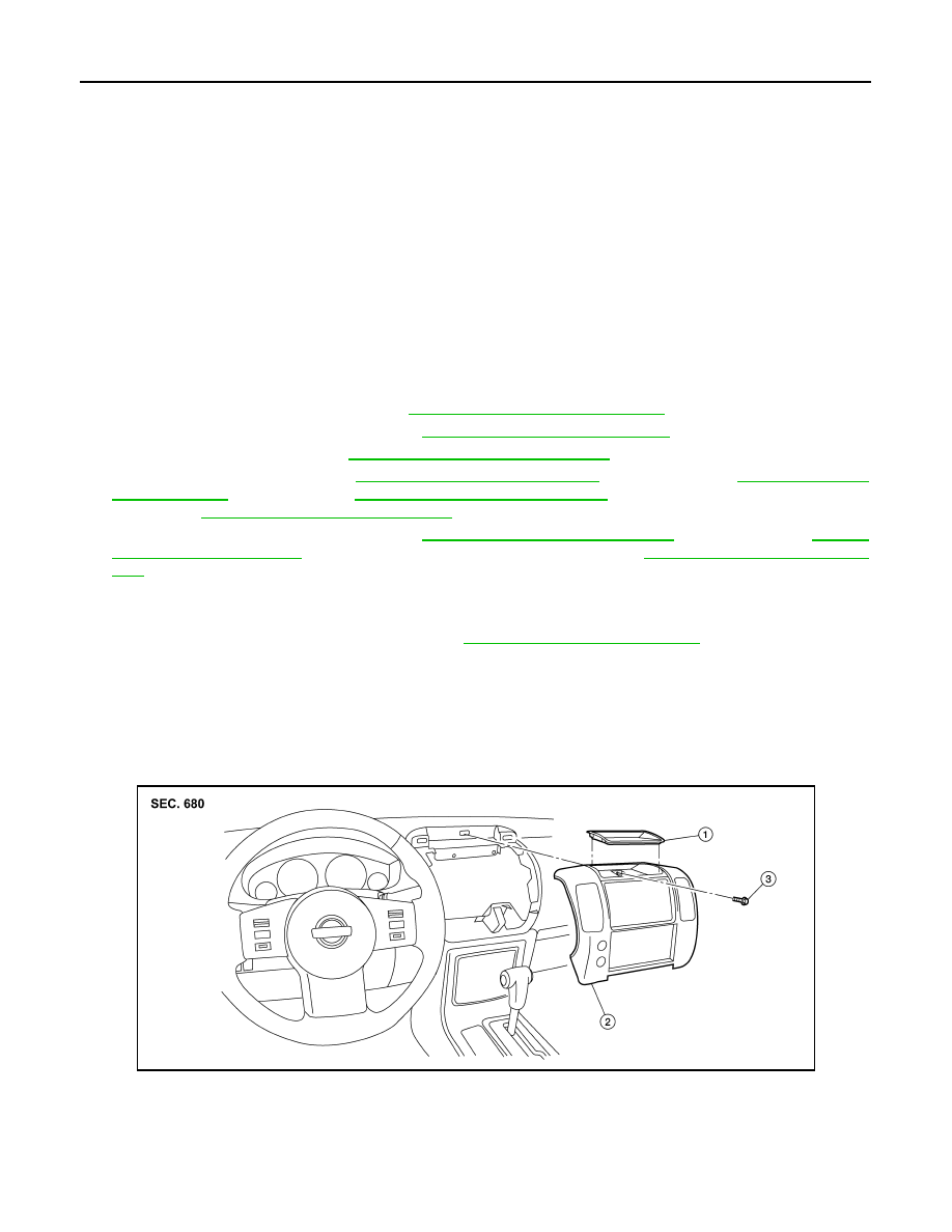
CLUSTER LID C -WITHOUT DISPLAY UNIT

Removal

CAUTION:

16. Center ventilator grill RH/LH

17.

Cluster lid D

18. AV control unit

19. A/C and AV switch assembly

20.

Lower glove box latch assembly

21. Lower glove box

22. Fuse block cover

23.

Lower glove box damper assembly 24. Lower instrument panel RH

25. Upper glove box door

26.

Upper glove box

27. Instrument side finisher

28. Instrument panel and pad assembly 29.

Passenger air bag module


AWJIA0463ZZ

1.

Storage tray

2.

Cluster lid C

3.

Cluster lid C screw

2010 Pathfinder

INSTRUMENT PANEL ASSEMBLY

IP-13

< ON-VEHICLE REPAIR >

C

D

E

F

G

H

I

K

L

M

A

B

IP

N

O

P

Before servicing, turn the ignition switch off, disconnect both battery cables and wait at lease three

minutes.

1. Remove A/T finisher. Follow the A/T FINISHER removal procedure.
2. Remove storage tray, then remove cluster lid C screw.
3. Pull cluster lid C rearward to release clips.
4. Disconnect harness connectors, then remove cluster lid C.

Installation

Installation is in the reverse order of removal.

CLUSTER LID C - WITH DISPLAY UNIT

Removal

CAUTION:

Before servicing, turn the ignition switch off, disconnect both battery terminals, then wait at least

three minutes.

1. Select neutral, then remove shift lever handle.
2. Remove A/T finisher.
3. Remove the center console bin screws and center console bin.
4. Remove cluster lid C bolts, then release the clips and remove cluster lid C.
5. Disconnect electrical connectors and remove cluster lid C.

Installation

Installation is in the reverse order of removal.

AWJIA0055ZZ

1.

Instrument panel

2.

Cluster lid C

A.

Cluster lid C bolt

Clip C103

Metal clip

2010 Pathfinder

IP-14

< ON-VEHICLE REPAIR >

INSTRUMENT PANEL ASSEMBLY

CLUSTER LID D

Removal

1. Remove A/T finisher.
2. Remove lower instrument panel LH.
3. Remove lower instrument panel RH.
4. Remove cluster lid C.
5. Disconnect the electrical connectors and remove cluster lid D.

Installation

Installation is in the reverse order of removal.

LOWER INSTRUMENT PANEL LH

Removal

1. Remove front pillar lower finisher. Refer to 

INT-17, "Removal and Installation"

.

2. Remove lower instrument panel LH, using power tool.
3. Pull rearward to release lower instrument panel LH.
4. Disconnect lower instrument panel LH harness connectors.

Installation

Installation is in the reverse order of removal.

AWJIA0056ZZ

1.

Cluster lid D

A.

Cluster lid D screw

LIIA1744E

2010 Pathfinder

INSTRUMENT PANEL ASSEMBLY

IP-15

< ON-VEHICLE REPAIR >

C

D

E

F

G

H

I

K

L

M

A

B

IP

N

O

P

CLUSTER LID A

Removal

1. Remove front pillar upper finisher. Refer to XX-XX, "*****".
2. Remove lower instrument panel LH. Refer to LOWER INSTRUMENT PANEL LH in this section.
3. Remove steering lock escutcheon.
4. Remove the screws and clips, then lift cluster lid A rearward in vehicle away from the instrument panel.

Installation

Installation is in the reverse order of removal. 

STEERING COLUMN COVER

Removal

1. Partially remove driver door weatherstrip and set aside. 
2. Remove front pillar lower finisher. Refer to 

INT-17, "Removal and Installation"

.

3. Remove lower intstrument panel LH. Refer to LOWER INSTRUMET PANEL LH in this section.
4. Remove the steering column cover screws, then remove both the upper and lower portions of the steering

column cover.

Installation

Installation is in the reverse order of removal.

A/T FINISHER

Removal

1. Remove cup holder finisher. 
2. Release the shift lever handle clip, then remove shift lever handle. Refer to 

TM-170, "Exploded view"

.

ALJIA0460ZZ

1.

Combination meter

2.

Cluster lid A

3.

Ignition key lamp assembly

4.

Steering lock escutcheon

Metal clip

AWJIA0057ZZ

1.

Cluster lid D

2.

Center console front base

3.

Cup holder finisher

4.

A/T finisher

Front

2010 Pathfinder

IP-16

< ON-VEHICLE REPAIR >

INSTRUMENT PANEL ASSEMBLY

3. Pull up to release clips and disconnect the connectors, then remove the A/T finisher.

Installation

Installation is in the reverse order of removal.

LOWER INSTRUMENT PANEL RH AND LOWER GLOVE BOX

Removal

1. Disconnect the negative battery terminal.
2. Remove front pillar lower finisher. Refer to 

INT-17, "Removal and Installation"

.

3. Remove lower instrument panel RH screws, using power tool.
4. Remove lower instrument panel RH and lower glove box.

Installation

NOTE:

Install upper glove box before installing lower glove box. 

Installation is in the reverse order of removal.

UPPER GLOVE BOX

Removal

1. Remove lower instrument panel RH and lower glove box.
2. Remove cluster lid C.
3. Remove upper glove box screws, using power tool.
4. Remove upper glove box.

Installation

Installation is in the reverse order of removal.

CENTER CONSOLE

Removal

1. Remove lower instrument panel RH and glove box. Refer to LOWER INSTRUMENT PANEL RH AND

GLOVE BOX in this section.

2. Remove cup holder finisher.
3. Remove A/T finisher. Refer to AT FINISHER in this section.
4. Remove center console screws, then lift center console rear base away from center console front base

and disconnect harness connectors.

: Vehicle front

5. Disconnect harness connectors, then remove center console front base.

WIIA1058E

2010 Pathfinder

INSTRUMENT PANEL ASSEMBLY

IP-17

< ON-VEHICLE REPAIR >

C

D

E

F

G

H

I

K

L

M

A

B

IP

N

O

P

Installation

Installation is in the reverse order of removal.

2010 Pathfinder

IP-18

< DISASSEMBLY AND ASSEMBLY >

CENTER CONSOLE ASSEMBLY

DISASSEMBLY AND ASSEMBLY

CENTER CONSOLE ASSEMBLY 

Exploded View

INFOID:0000000005259202

Disassembly and Assembly

INFOID:0000000005259203

LOWER GLOVE BOX

Disassembly

1. Remove fuse block cover.
2. Remove damper hook.
3. Remove lower glove box latch cover. 
4. Remove lower glove box latch assembly.

Assembly

Assembly is in the reverse order of disassembly.

UPPER GLOVE BOX

Disassembly

1. Remove upper glove box door screws.
2. Remove upper glove box door.

1.

Upper glove box

2.

Upper glove box door

3.

Lower instrument panel RH

4.

Fuse block cover

5.

Lower glove box latch assembly cover 6.

Lower glove box

7.

Lower glove box latch assembly

8.

Damper hook

9.

Lower glove box damper

WIIA1049E

2010 Pathfinder

CENTER CONSOLE ASSEMBLY

IP-19

< DISASSEMBLY AND ASSEMBLY >

C

D

E

F

G

H

I

K

L

M

A

B

IP

N

O

P

Assembly

Assembly is in the reverse order of disassembly.

Center Console

Disassembly

1. Remove center console. Refer to 

IP-12, "Removal and Installation"

.

2. Remove center console lid.
3. Remove latch from center console lid.
4. Remove hinge from center console lid.
5. Remove rear finisher assembly.
6. Remove rear cup holder assembly.
7. Remove DVD player, if equipped. Refer to 

AV-148, "Removal and Installation of DVD Player"

 for MID

AUDIO, 

AV-301, "Removal and Installation of DVD Player"

 for BOSE AUDIO WITHOUT NAVIGATION, or

AV-468, "Removal and Installation of DVD Player"

 for BOSE AUDIO WITH NAVIGATION.

8. Disconnect center console harness connectors.
9. Remove cup holder insert and cup holder assembly.
10. Remove center console bin.
11. Remove center console bracket.

AWJIA0058ZZ

1.

Console bin

2.

A/T finisher

3.

Ash tray

4.

Center console front base

5.

Cup holder finisher

6.

Bracket

7.

Center console rear base

8.

Bracket DVD

9.

Wire harness bracket

10. Rear finisher assembly

11. Rear cup holder assembly

12. Ventilator console grille (if equipped)

13. Rear air control (rear) (if equipped) 14. Hinge

15. Center console lid

16. Center console bin

17. Cup holder insert

18. Cup holder assembly

A.

Screw

B.

Bolt

Vehicle front

2010 Pathfinder


Content      ..     476      477      478      479     ..